2 input circuit signal allocation, 24 (c) parameter indications, Pn50a: pn50b – Yaskawa Sigma II Series SGMVH User Manual
Page 173
7 Digital Operator/Panel Operator
7.3.2 Input Circuit Signal Allocation
7-24
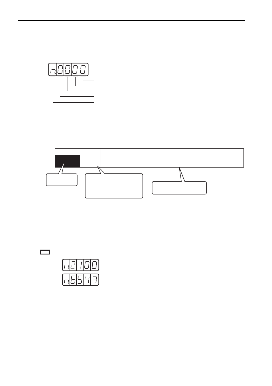
(c) Parameter Indications
Each digit of the function selection parameters is defined as the hexadecimal display. The parameter display
example shows how parameters are displayed in digits for set values.
For details on each digit of the parameter, see 11.3.2 List of Parameters.
7.3.2 Input Circuit Signal Allocation
Each input signal is allocated to a pin of the input connector CN1 by setting the parameter.
The following table shows detailed allocation.
(1) Factory Setting (Pn50A.0 = 0)
The factory setting for the input signal allocation is as follows.
means factory setting.
• Pn000.0 or n.xxx: Indicates the value for the 1st digit of parameter Pn000.
• Pn000.1 or n.xxx: Indicates the value for the 2nd digit of parameter Pn000.
• Pn000.2 or n.xxx: Indicates the value for the 3rd digit of parameter Pn000.
• Pn000.3 or n.xxx: Indicates the value for the 4th digit of parameter Pn000.
For the hexadecimal display only
1st digit
2nd digit
3rd digit
4th digit
Pn50A
n.2
n.8
The number of the
parameter
Parameter
Meaning
This section explains the
details of the function selection.
This blank shows the setting
value of the function selection,
as well as the state condition
on the panel operator and the
digital operator (JUSP-OP02A-2).
Input the forward run prohibited signal (P-OT) from CN1-42 (Factory setting).
Forward run prohibited signal (P-OT) is disabled (Forward rotation allowed).
Pn50A:
Pn50B: