3 electrical inspection of an encoder – HEIDENHAIN TNC 415 (259 9x0) Service Manual User Manual
Page 85
SERVICE MANUAL TNC 415B/425
Page 80
Issue: 20.08.95
13.3 Electrical Inspection of an Encoder
In order to give a precise statement on the electrical function of an encoder, it must be measured with a
phase angle measuring unit (PWM), an oscilloscope and a leak tester. (see operating instructions of encoder
diagnostic set)
If no phase angle measuring unit is available, the electrical state of the cable, the lamp and the photocells of
an encoder can be checked with an ohmmeter. The following resistances must be measured at the connector
of the encoder:
Possible measurements at an encoder with current interface (7 - 16µA)
•
encoder connector housing against machine chassis < 1
Ω
(external shield)
•
encoder connector housing against PIN 9 (internal shield - external shield) R =
∞
•
encoder connector housing against PIN 1 to PIN 8 (external shield - signal lines ) R =
∞
•
PIN 9 against PIN 1 to PIN 8 (internal shield - signal line) R =
∞
•
pin 1 against pin 2
0°
•
pin 2 against pin 1
0°
•
pin 5 against pin 6
90°
•
pin 6 against pin 5
90°
•
pin 7 against pin 8
RP
1)
•
pin 8 against pin 7
RP
1)
•
pin 3 against pin 4
2)
(switch poles of ohmmeter)
(switch poles of ohmmeter)
(switch poles of ohmmeter)
(approx. 5 - 30
Ω
)
The measured values should
approximately equal.
1)
If encoders with selectable reference mark are used, different resistance values can be measured
(or no resistance), depending on the type of activation.
2)
The encoder check (pin 3 against pin 4) can only be carried out, if the encoder light unit is a lamp.
If the encoder features an amplifier section, the light unit cannot be checked at all. With encoders
with infrared diodes, a resistance in the conducting direction can be measured between pin 3 (+)
and pin 4 (-).
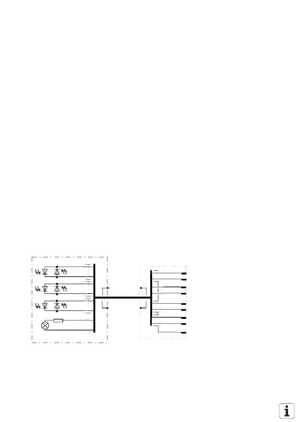
Basic Circuit Diagram with Sinusoidal Signals (7 - 16µA)
0°
90°
RI
R1
gn
ye
bl
re
gr
pi
br
wh
external shield
gn 1
ye 2
br 3
wh 4
bl 5
re 6
gr 7
pi 8
wh/br 9
0° +
0° -
La +
La -
90° +
90° -
RI +
RI -
internal shield
Encoders with square-wave signals can only be tested with a phase angle measuring unit (PWM).