HEIDENHAIN TNC 415 (259 9x0) Service Manual User Manual
Page 167
SERVICE MANUAL TNC 415B/425
Page 162
Issue: 20.08.95
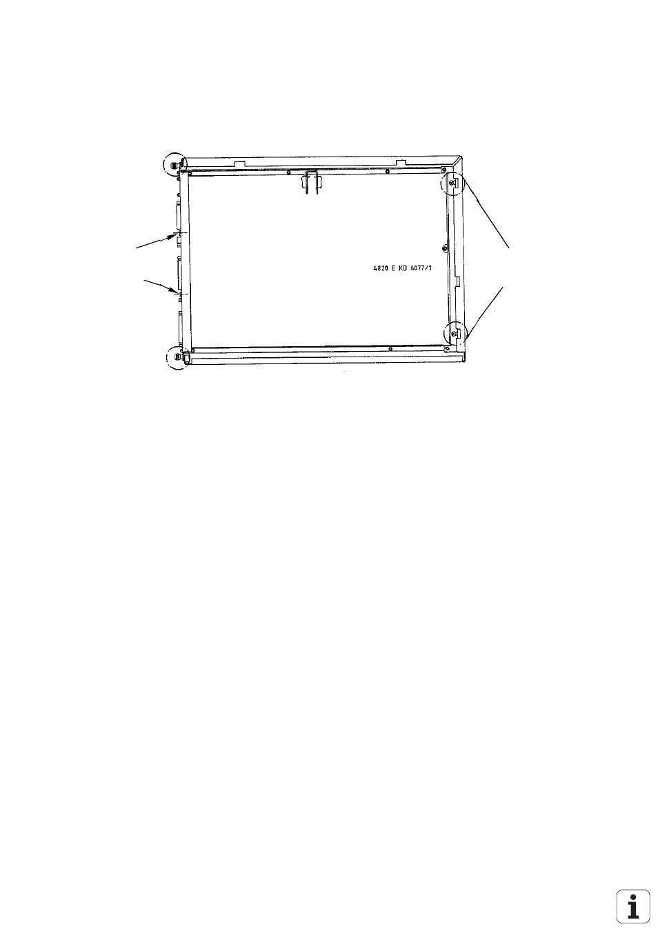
e) Loosen/remove fixing screws
Remove
knurled screw
Loosen
fixing screws
Remove
knurled screw
Remove
fixing screws
f) Lift out the PLC graphics board and insert the new board.
21.5.3 Mounting the PLC Graphics Board
The PLC graphics board is mounted in the reverse order that it was dismounted.
a) Insert and secure the PLC graphics board.
b) Engage the connectors.
*
Observe that no connectors are switched
!
c) Close the logic unit and the lock.
d) Switch on the main switch.
e) Carry out offset adjustment with code number (see section 18.5).
Exchange is now finished.
*
Warning!
Send and store the boards only in the original packaging material that protects
them from acquiring static charge. Never use conventional plastics to wrap the boards in.