Emergency stop, Relay ext. dc voltage missing, 1 wiring of the emergency stop interface – HEIDENHAIN TNC 415 (259 9x0) Service Manual User Manual
Page 149
SERVICE MANUAL TNC 415B/425
Page 144
Issue: 20.08.95
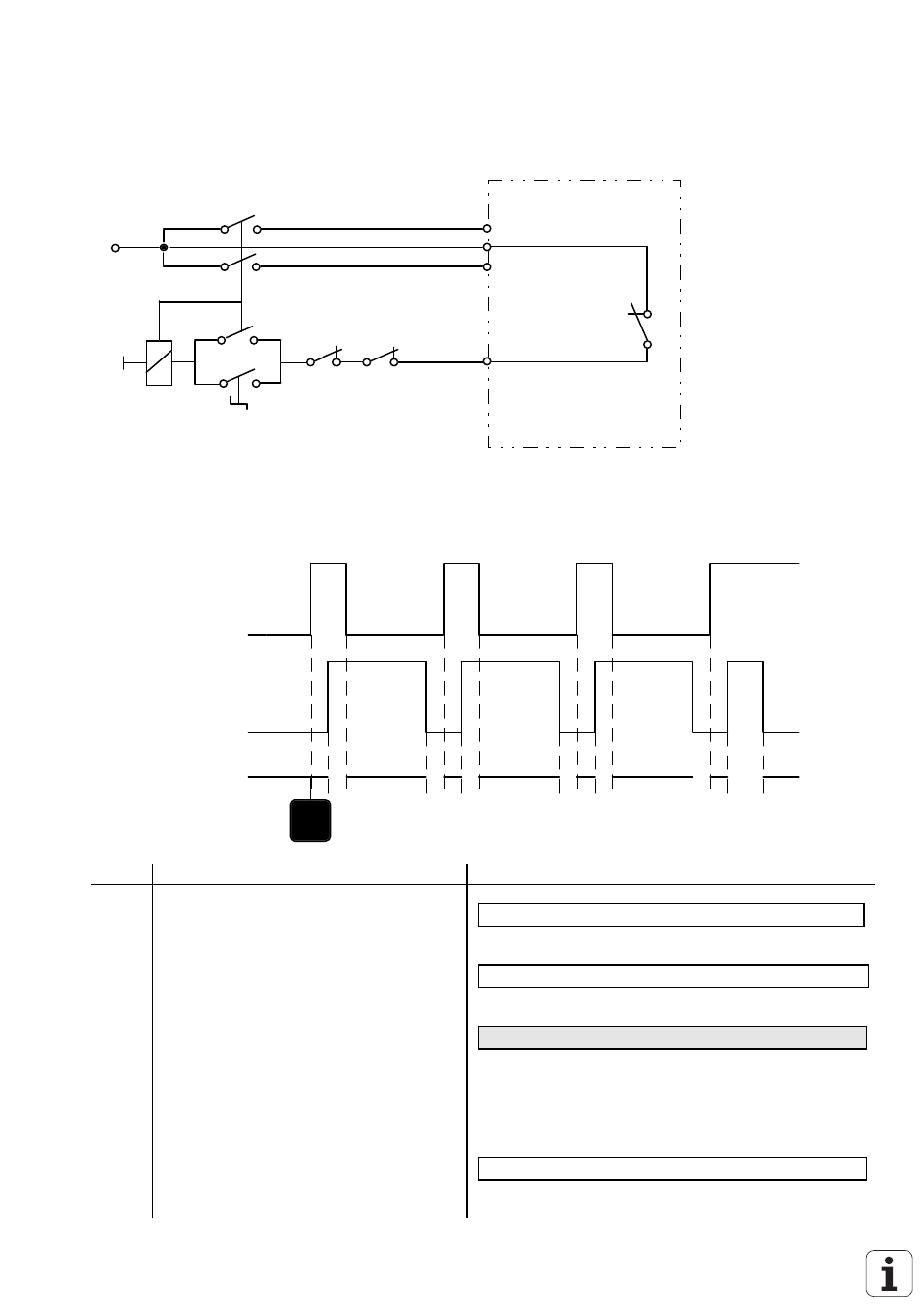
19.6.1 Wiring of the EMERGENCY STOP Interface
+24V
0V
Control Voltage
EXTERNAL
EMERG. STOP
X41/34
Machine Tool
Limit Switch
24V for the PLC outputs
INPUT: Acknowledgement
"Control Ready for Operation"
INTERNAL
EMERG. STOP
(blinking)
OUTPUT: "Control Ready
for Operation"
LE 415B/425
X44/1
X44/2
X42/4
24V_A Power supply
19.6.2 TNC 415B/425 Flow Diagram
1
2
3
3
3
2
2
4
max.
114 ms
max.
114 ms
max.
114 ms
CE
EMERG. STOP
communication proc.
geometry proc.
CLP processor
OUTPUT: "Control
Ready for Operation"
INPUT: Acknowledgement
"Control Ready for Operation"
EMERG. STOP
EMERG. STOP
Time
Remarks
Error Message
1
POWER INTERRUPTED
2
Waiting for control voltage
RELAY EXT. DC VOLTAGE MISSING
3
After switching off the output
"Control Ready for Operation", the
"Acknowledgement Control Ready for
Operation" must be switched off within
114 ms; otherwise the blinking error
message is generated.
EMERGENCY STOP DEFECTIVE YX
YX = 1(
= Communication processor
1)
= Geometry processor
1.
= CLP processor
4
If the acknowledgement is switched off
during operation, the error message is
displayed.
EMERGENCY STOP