Measuring setup to check the analogue outputs, Observe the safety instructions – HEIDENHAIN TNC 415 (259 9x0) Service Manual User Manual
Page 126
SERVICE MANUAL TNC 415B/425
Page 121
Issue: 20.08.95
When the override potentiometer is turned to the right, the control outputs an analogue voltage which is
increased proportionally to the servo lag up to a maximum value of 10V. The control operates correctly,
if a voltage of 10V
±
0.1V can be measured at the test adapter with the multimeter. If no voltage can be
measured, switch off the main switch, unplug the connector X8 from the logic unit, disconnect the nominal
value line from the servo amplifier and test this line for short-circuit. If the nominal value line is in order,
connect X8 to the logic unit again (leave the nominal value line disconnected), switch on the main switch and
repeat the measurement with reference mark traverse. If an analogue voltage can be measured now, the
control operates correctly. If no voltage can be measured, the analogue output of the logic unit is probably
defective.
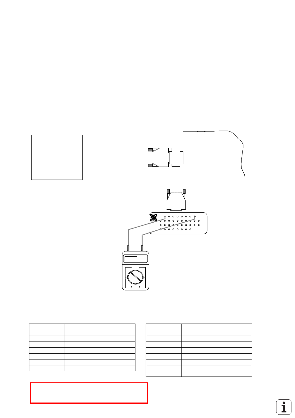
Measuring Setup to Check the Analogue Outputs
servo
amplifier
ANALOGUE
logic unit
X8
test adapter
multimeter
5.15V
X8 Nominal value output for 1, 2, 3, 4, 5, S
flange socket with female insert (15-pin
Pin No.
Signal
Pin No.
Signal
1
analogue output 1
11
0V analogue output 2
3
analogue output 2
13
0V analogue output 3
5
analogue output 3
14
0V analogue output 4
7
analogue output 4
6
0V analogue output 5
4
analogue output 5
15
0V analogue output S axis
8
analogue output S axis
housing
external shield = housing
9
0V analogue output 1
2, 10, 12
do not assign
*
Observe the safety instructions!