Connectors on the visual display units, 4 connectors on the visual display units – HEIDENHAIN TNC 415 (259 9x0) Service Manual User Manual
Page 46
SERVICE MANUAL TNC 415B/425
Page 43
Issue: 20.08.95
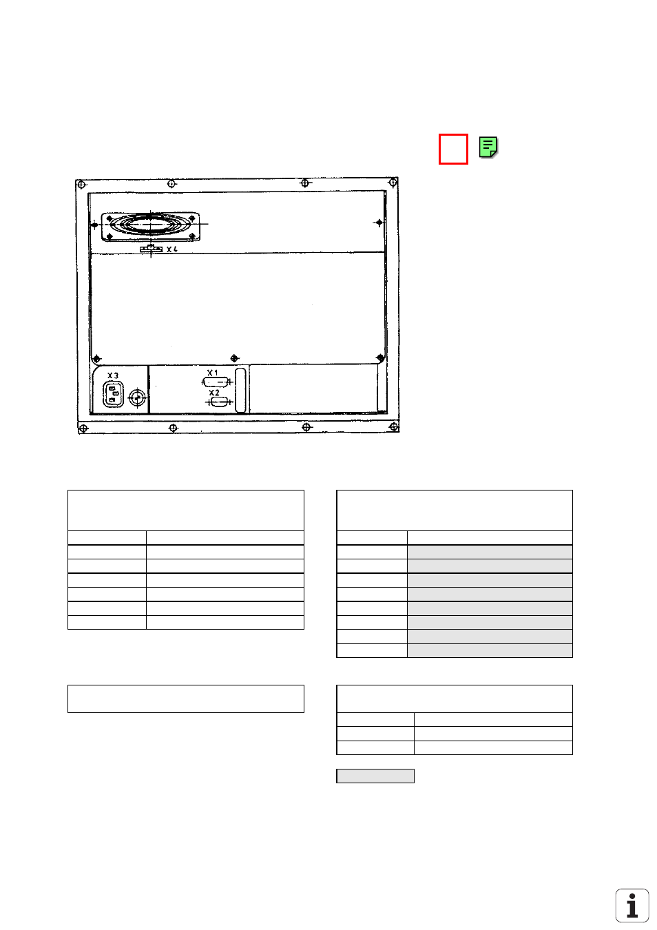
6.4 Connectors on the Visual Display Units
6.4.1 Connectors on the Visual Display Unit BC 110
6.4.2 Pin Layout: Visual Display Unit BC 110
X1 Connection to the Logic Unit
flange socket with male insert (15-pin)
X2 Connection of the soft keys to the
Keyboard Unit
flange socket with male insert (9-pin)
Pin No.
Assignment
Pin No.
Assignment
7
R analogue
1
SL0
9
V-SYNC
2
SL1
10
H-SYNC
3
SL2
11
0V
4
SL3
14
G analogue
6
RL15
15
B analogue
7
RL14
8
RL13
9
RL12
X3 Power Connection
Euro connector
X4 DC Connection for Integral Fan
terminal strip (2-pin)
Pin No.
Assignment
1
+24V
2
0V
= key matrix
This manual is related to the following products: