1 plc power supply: block diagram – HEIDENHAIN TNC 415 (259 9x0) Service Manual User Manual
Page 64
SERVICE MANUAL TNC 415B/425
Page 60
Issue: 20.08.95
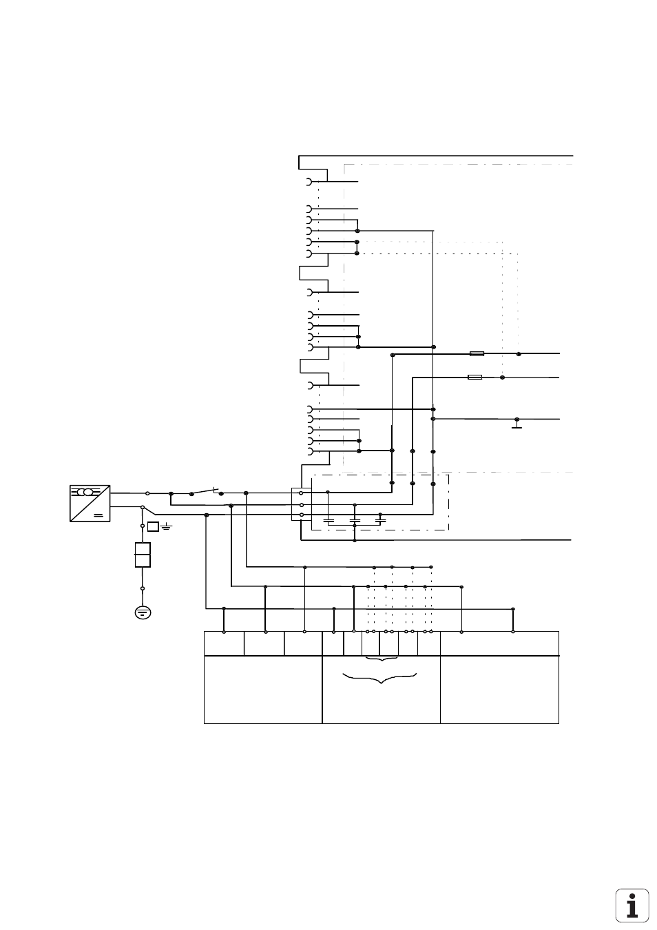
10.4.1 PLC Power Supply: Block Diagram
F 3.15A
.
.
.
33
34
35
36
1
X46
machine
operating
panel
37
1
X42
34
35
36
37
.
.
PLC input
1
X41
.
.
34
35
36
37
PLC output
33
VDE 0550
+24V
0V
X44
1
2
3
24V_A
24V
0V
F 1A
+24V_A
+24V
0 V
10
11
12
3
2
1
wh/bk
wh
bk
to internal
PLC
PLC board version
03
01/02
for testing
only
1
0
B
can be switched off
via ext. EMERG. STOP
PL 400
(option)
not with
PL 405
24V or 24V_A
PL 405/410
(option)
PA 110
(option)
X12
X3/12
X13
X9 X10 X11 X12 X13 X14
1)
1)
1)
1)
X6/1
1)
can be powered with 24V or 24V_A
X6/2
for testing
only
PLC board versions
X44 Pin 1, +24V_A (PLC can be switched off): power supply for the PLC outputs O0 - O23.
X44 Pin 2, +24V (PLC cannot be switched off): power supply for the PLC outputs O24 - O30 and output
"control ready for operation"; power supply for PLC graphics
board.