Connector designation and pin layout, Connectors on the logic unit le 415b/425 – HEIDENHAIN TNC 415 (259 9x0) Service Manual User Manual
Page 23
SERVICE MANUAL TNC 415B/425
Page
20
Issue: 20.08.95
6.
Connector Designation and Pin Layout
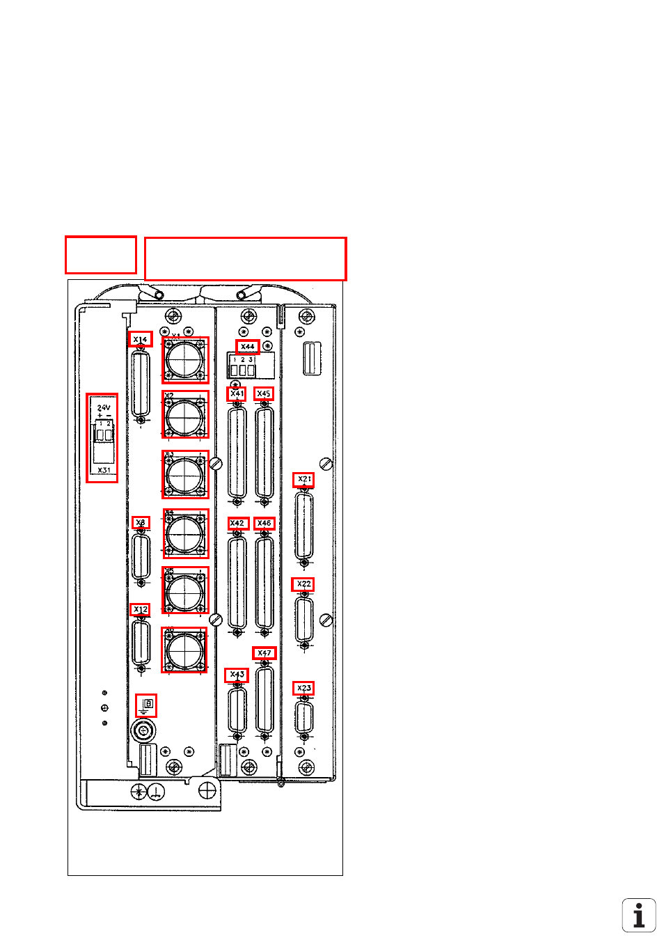
6.1 Connectors on the LOGIC UNIT LE 415B/425
6.1.1 Connector Designation LOGIC UNIT LE 415B/425
LE 415B
CLP board
X1
= nominal value output 1, 2, 3, 4, 5, S
X12 = triggering touch probe
X14 = measuring touch probe
B
PLC graphics board
X41 = PLC output
X42 = PLC input
X43 = visual display unit (BC)
X44 = 24V power supply for PLC
X45 = TNC keyboard unit (TE)
X46 = machine operating panel
X47 = PLC I/O board
Processor board
X21 = RS-232-C data interface
X22 = RS-422 data interface
X23 = electronic handwheel
X31 = 24V- power supply for NC
This manual is related to the following products: