3 checking the plc inputs and outputs – HEIDENHAIN TNC 415 (259 9x0) Service Manual User Manual
Page 139
SERVICE MANUAL TNC 415B/425
Page 134
Issue: 20.08.95
19.3 Checking the PLC Inputs and Outputs
The test unit (see section 20) can be used to check the PLC inputs and outputs on the logic unit
(X41, X42, X46). The voltage level of the PLC inputs and the output current of the PLC outputs
on the PL 400/405/410 can be measured directly at the terminals.
19.3.1 PLC Inputs
The PLC inputs can be checked as follows:
•
Connect the test unit between LE and PLC (measure directly at the PL boards).
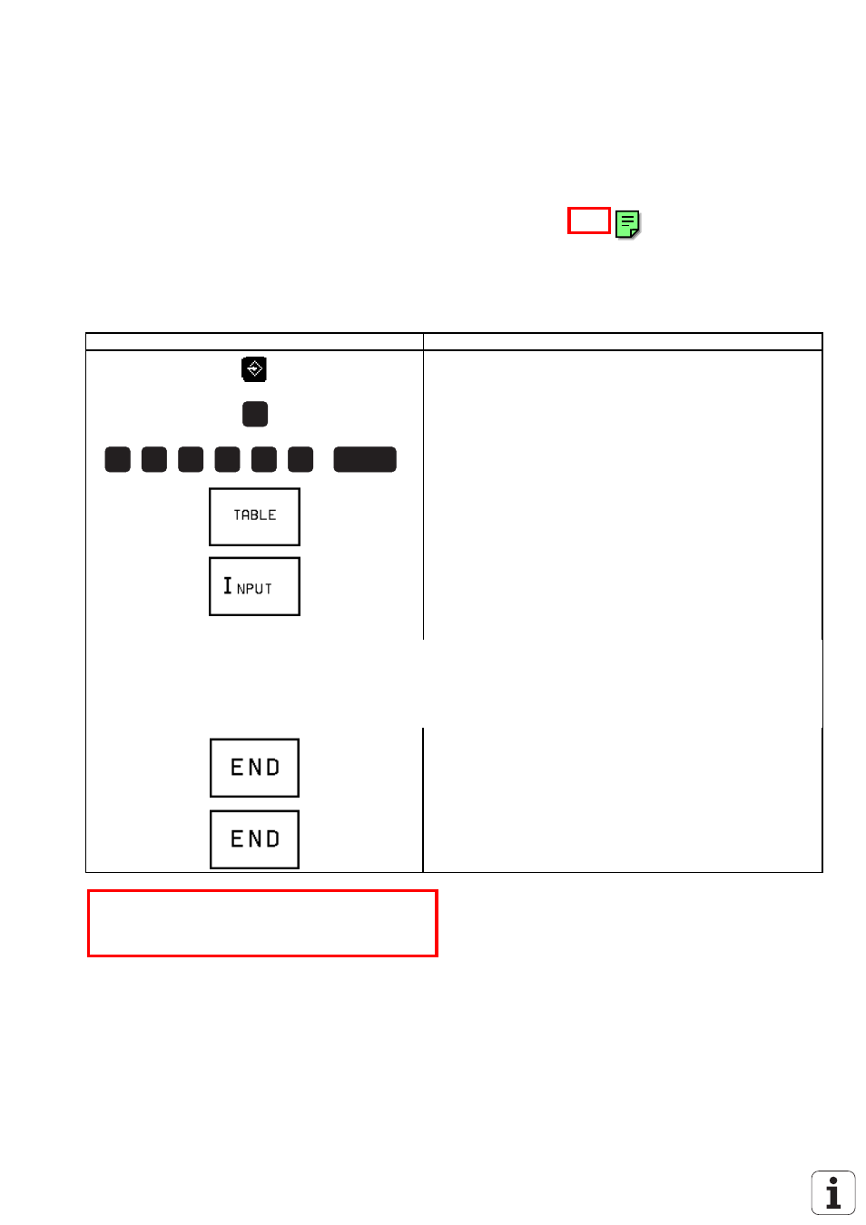
Press Key
Function
MOD
8
0
7
6
6
7
ENT
TNC in operating mode PROGRAMMING/EDITING
Prepare TNC for input of code number
Enter code number, confirm with ENT
Call TABLE function
Display of input table
Now the logic states of the inputs are displayed on the screen. They must correspond to the voltage levels
of the corresponding inputs (voltage levels: see section 19.1). If there is a difference and the input voltage
is correct, the input board of the PLC graphics board or the PLC I/O board PL 400/405/410 is defective.
Exit the TABLE function
TNC in operating mode PROGRAMMING/EDITING
*
Observe the safety instructions!