HEIDENHAIN TNC 415 (259 9x0) Service Manual User Manual
Page 35
SERVICE MANUAL TNC 415B/425
Page 32
Issue: 20.08.95
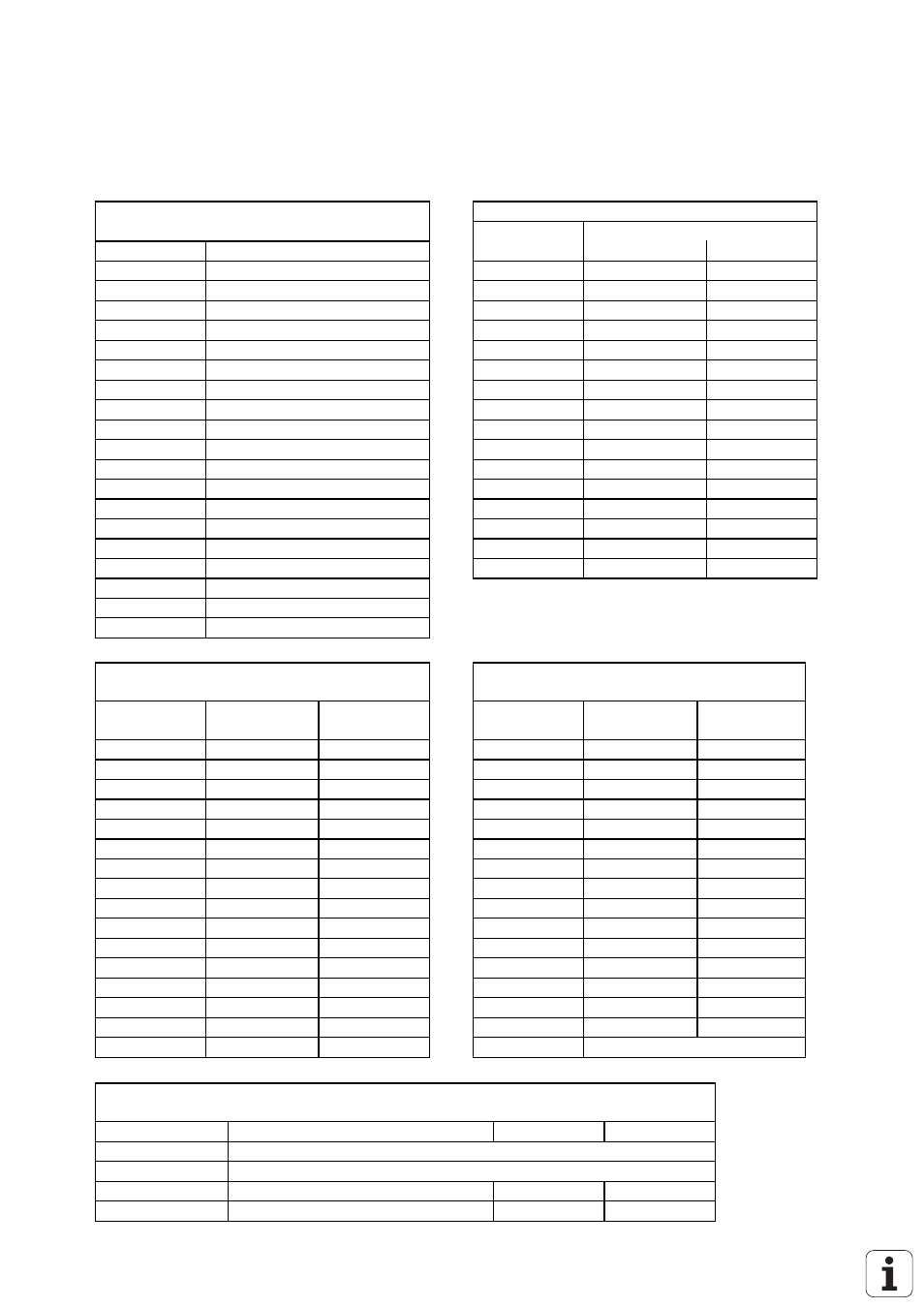
6.2.4 Pin Layout: PL 405
X1 Connection to Logic Unit or
X3 PLC Inputs
to 1. PL
Assignment
Pin No.
Assignment
Pin No.
as 1. PL
as 2. PL
1,2,3
0V
1
I64
I192
5.6.17.18
do not assign
2
I65
I193
4
serial IN 2
3
I66
I194
7
-RESET
4
I67
I195
8
WRITE EXTERN
5
I68
I196
9
-WRITE EXTERN
6
I69
I197
10
-O5
7
I70
I198
11
-O3
8
I71
I199
12
-O1
9
I72
I200
13
shield
10
I73
I201
14, 15
+12V
11
I74
I202
16
board ID (PK)
12
I75
I203
19
serial IN 1
13
I76
I204
20
control ready for operation
14
I77
I205
21
-serial OUT
15
I78
I206
22
serial OUT
16
I79
I207
23
-O4
24
-O2
25
-O0
X4 PLC Inputs
X8 PLC Outputs
and "Control Ready for Operation"
Pin No.
Assignment
as 1. PL
as 2. PL
Pin No.
Assignment
as 1. PL
as 2. PL
1
I80
I208
1
O48
O80
2
I81
I209
2
O49
O81
3
I82
I210
3
O50
O82
4
I83
I211
4
O51
O83
5
I84
I212
5
O52
O84
6
I85
I213
6
O53
O85
7
I86
I214
7
O54
O86
8
I87
I215
8
O55
O87
9
I88
I216
9
O56
O88
10
I89
I217
10
O57
O89
11
I90
I218
11
O58
O90
12
I91
I219
12
O59
O91
13
I92
I220
13
O60
O92
14
I93
I221
14
O61
O93
15
I94
I222
15
O62
O94
16
I95
I223
16
control ready for operation
X9, X10, X13, X14 PL 405 Power Supply
Terminal
Assignment
as 1. PL
as 2. PL
X9
0V
X10
+24 V- logic supply and "Control Ready for Operation"
X13
+24 V- output supply
O48 - O55
O80 - O87
X14
+24 V- output supply
O56 - O62
O88 - O94