Measuring system 1, Measuring system 2, Measuring system 3 – HEIDENHAIN TNC 415 (259 9x0) Service Manual User Manual
Page 25: Measuring system 4, Measuring system 5, Measuring system s ( ), Nominal value output 1, 2, 3, 4, 5, s, X12 = triggering touch probe, X31 = 24v- power supply for nc, Encoder 1
SERVICE MANUAL TNC 415B/425
Page 22
Issue: 14.11.06
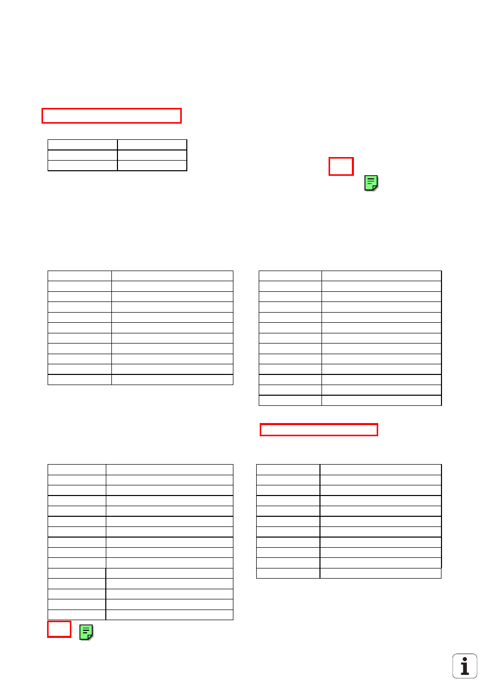
6.1.2 Pin Layout: POWER SUPPLY LE 415B/425
X31 Power Supply (NC)
terminal strip (pluggable) 2-pin
Pin No.
Assignment
1
+ 24 V
2
0V
6.1.3 Pin Layout: CLP Board LE 415 B
X1,X2,X3,X4,X5 Encoders 1,2,3,4,5
(Position)
X6 Spindle Encoder (Position)
sinusoidal input,
current interface 7-16µA
flange socket with female insert (9-pin, Conei)
square-wave encoder (TTL)
flange socket with female insert (12-pin, Conei)
Pin No.
Assignment
Pin No.
Signal Designation
1
0°+
5
Ua1
2
0°-
6
-Ua1
5
90°+
8
Ua2
6
90°-
1
-Ua2
7
RP+
3
Ua0
8
RP-
4
-Ua0
3
+ 5 (Up)
7
-UaS
4
0 V (U
usable comp.
)
(2)
+ 5V (sense)
9
internal shield
12
+ 5V (Up)
housing
external shield = housing
(11)
0 V (sense)
10
0 V (U
usable comp.
)
9 (via spring)
shield = housing
X8 Nominal Value Output 1,2,3,4,5,S
flange socket with female insert
(15-pin, D-SUB)
flange socket with female insert
(15-pin, D-SUB)
Pin No.
Signal Designation
Pin No.
Signal Designation
1
analogue output 1
1
internal shield
3
analogue output 2
3
standby
5
analogue output 3
4
start
7
analogue output 4
5
+ 15V
4
analogue output 5
6
+ 5V (Up)
8
analogue output spindle
7
-battery warning
9
0V analogue output 1
8
0 V (U
usable comp.
)
11
0V analogue output 2
9
trigger signal
13
0V analogue output 3
10
-trigger signal 1)
14
0V analogue output 4
2, 11 to 15
not assigned
6
0V analogue output 5
15
0V analogue output spindle
1) stylus at rest = high level
housing
external shield = housing
2,10,12
do not assign