Measuring setup to check the analogue outputs, Observe the safety instructions – HEIDENHAIN TNC 415 (259 9x0) Service Manual User Manual
Page 128
SERVICE MANUAL TNC 415B/425
Page 123
Issue: 20.08.95
When the override potentiometer is turned to the right, the control outputs an analogue voltage which is
increased proportionally to the servo lag up to a maximum value of 10V. The control operates correctly,
if a voltage of 10V
±
0.1V can be measured at the test adapter with the multimeter. If no voltage can be
measured, the analogue output of the logic unit is probably defective.
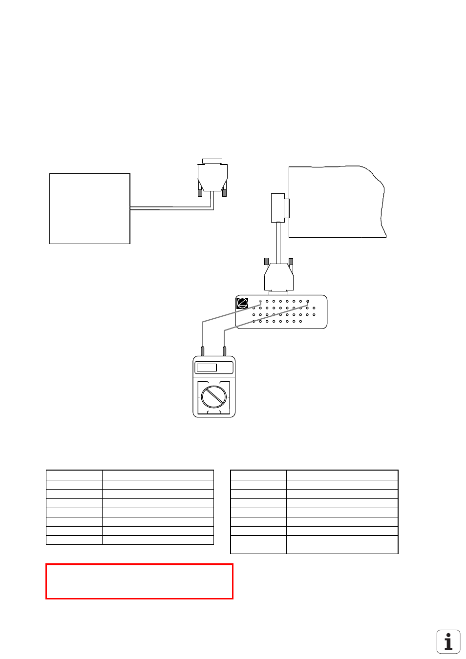
Measuring Setup to Check the Analogue Outputs
servo
amplifier
DIGITAL
logic unit
X8
test adapter
multimeter
5.15V
the cable between nominal
value output and servo amplifier !
Disconnect
X8 Nominal value output for 1, 2, 3, 4, 5, S
flange socket with female insert (15-pin)
Pin No.
Signal
Pin No.
Signal
1
analogue output 1
11
0V analogue output 2
3
analogue output 2
13
0V analogue output 3
5
analogue output 3
14
0V analogue output 4
7
analogue output 4
6
0V analogue output 5
4
analogue output 5
15
0V analogue output S axis
8
analogue output S axis
housing
external shield = housing
9
0V analogue output 1
2, 10, 12
do not assign
*
Observe the safety instructions!