Checkpoint console, 5 vdc measurement, 5 vdc adjustment – Gasboy Site Controller III Start-Up User Manual
Page 76: Figure 9-4: checkpoint +5 vdc measurement point, Warning
DC Power Measurement and Adjustment
Page 64
MDE-4375 CFN Series Site Controller III Start-Up Manual · June 2005
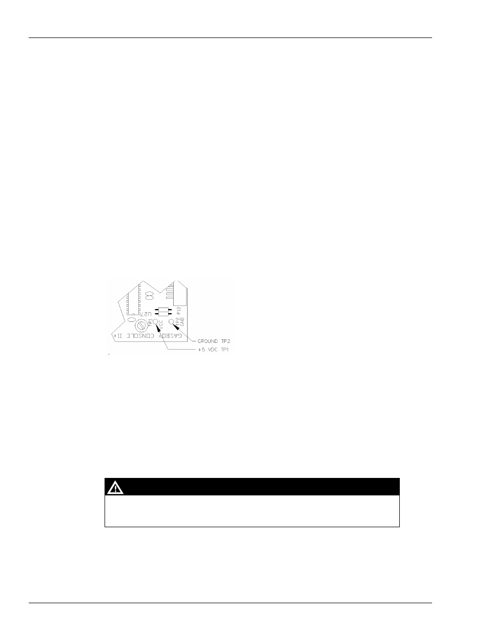
Checkpoint Console
+5 VDC Measurement
1
Turn off power to the console.
2
Remove the four screws from the bottom of the console and carefully separate the upper
housing from the lower housing.
3
Turn on the power to the console.
4
On the CPU PCB, measure at the TP1 and TP2 test points, with the positive (+) probe on TP1
and the negative (-) probe on TP2 (
The voltage should be +5.00 to +5.10 VDC.
• If the voltage does not fall within this range, adjustment is necessary. Follow the steps in
• If the voltage is within tolerance, skip to
“+12 VDC Measurement” on page 65
Figure 9-4: Checkpoint +5 VDC Measurement Point
+5 VDC Adjustment
1
Turn off the power to the console.
2
Remove the three screws that hold the power supply cover onto the supply; remove the cover.
3
Attach the meter probes to TP1 and TP2 on the CPU PCB.
4
Turn the AC POWER switch back on.
5
Using a 1/8 inch or smaller plastic, flat-blade screwdriver, adjust the power supply to +5 VDC
by turning the screw clockwise to increase voltage, counterclockwise to decrease voltage.
Turn the screw slightly to judge how sensitive the adjustment is.
Be careful not to touch anything but the adjustment screw. High voltage exists at
various points on the supply.
WARNING