Island card reader, 5 vdc measurement, 5 vdc adjustment – Gasboy Site Controller III Start-Up User Manual
Page 74: Figure 9-2: icr +5 vdc measurement point
DC Power Measurement and Adjustment
Page 62
MDE-4375 CFN Series Site Controller III Start-Up Manual · June 2005
5
Measure the +12 VDC between the red (+) and black (-) wires (
).
The voltage should be +11.50 to +15.50 VDC depending on the type and number of pulsers
and the number of relays energized.
6
Measure the POWER FAIL between the yellow (+) and black (-) wires (
The voltage should be +4.75 to +5.05 VDC.
Note: There are no adjustments for these voltages.
7
Turn off the AC and DC power switches.
8
Replace the black plastic cover on the connector and turn the AC and DC power switches back
on.
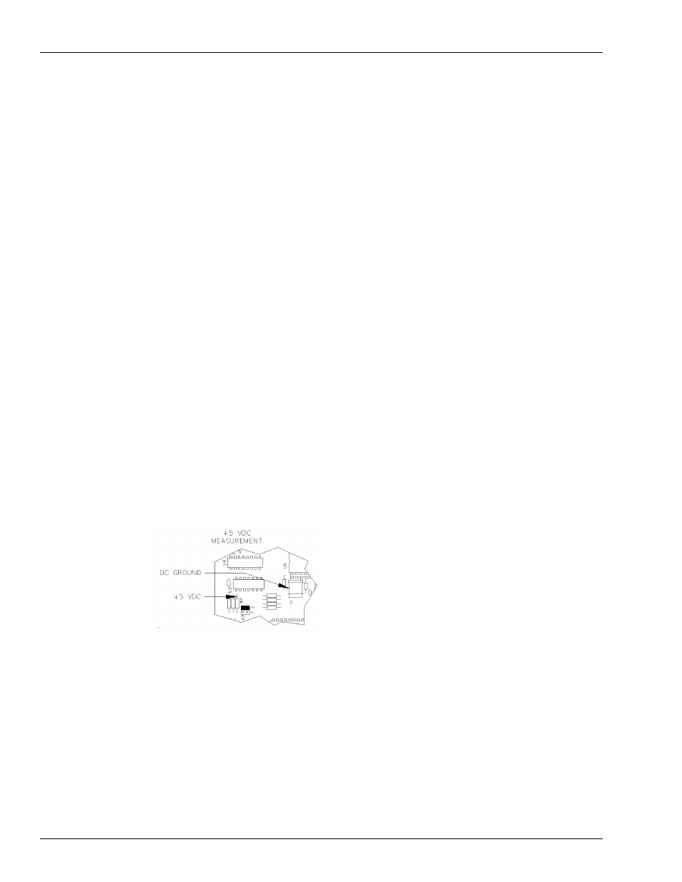
Island Card Reader
+5 VDC Measurement
1
Unlock, unscrew, and lower the face of the island card reader.
2
Measure the +5 VDC between the top of the resistor R7 (+) and the case of crystal Y1 (-)
(
The voltage should be +5.00 to +5.10 VDC.
• If the voltage does not fall within this range, adjustment is necessary. Follow the steps in
• If the voltage is within tolerance, skip to
“+12 VDC Measurement” on page 63
Figure 9-2: ICR +5 VDC Measurement Point
+5 VDC Adjustment
1
Turn off the AC POWER switch in the island card reader.
2
Remove the two white connectors on the power supply labeled DC OUT and AC IN.
3
Remove the four 5/32-inch nuts on each corner of the power supply, and remove the supply.
4
Being careful that it does not touch any of the circuits on the front door, lay the power supply
on a non-conductive surface (such as heavy plastic or cardboard).