Fluorescent display board, Exit from diagnostic self-test mode by pressing 9 – Gasboy Site Controller III Start-Up User Manual
Page 67
MDE-4375 CFN Series Site Controller III Start-Up Manual · June 2005
Page 55
Component Power-Up and Configuration
To configure the console:
1
Turn the key to MGR position and press the NO SALE key.
Access diagnostic mode, self-test 7, if necessary. See the Check Point Reference Manual if
further assistance is required. The message ***Configuration** appears and the display
scrolls through the keystrokes needed to change the values. Then the first option appears. If
the value selected for the option is the default value, the option is enclosed in asterisks (*). If
the value is not the default, the option is enclosed in minus signs (-).
2
Accept the defaults or change the values for any of the configuration options using the
following keys:
3
Exit from diagnostic self-test mode by pressing 9.
Fluorescent Display Board
ENTER
accepts the displayed value and displays the next configuration option.
PREV
selects the currently displayed option value and displays the previous option. For example,
if you’re on keyswitch type and press this key, console address is displayed.
1
displays the next value for that option. To accept that option and go on to the next option,
press ENTER.
2
displays the default value for the option. To accept that option and go on to the next option,
press ENTER.
0
exits the configuration mode and saves your changes.
7
returns you to the initial configuration display.
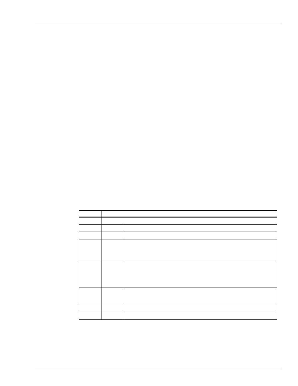
Switch
Function
SW1-1
Not used
SW1-2
Not used
SW1-3
Not used
SW1-4
MSTR
Open = display only (the characters are only displayed)
Closed = display and transmit to customer display (the VF driver transmits characters
through its serial interface and simultaneously displays them.)
Note: Must be closed when console is connected to a customer display.
SW1-5
SLAV
Open = VF driver used in console (the VF driver displays characters received through
its parallel interface)
Closed = VF driver not used in console (the VF driver displays all characters received
through its RS-485 interface)
Note: Must be open when VF driver is used in the console.
SW1-6
TEST
Open = normal mode (the VF driver functions normally)
Closed = test mode (with the CPU interface ribbon cable disconnected, the VF driver
displays a rotating barber-pole pattern self-test)
SW1-7
Not used
SW1-8
Not used