Caution – Gasboy Site Controller III Start-Up User Manual
Page 55
MDE-4375 CFN Series Site Controller III Start-Up Manual · June 2005
Page 43
Jumpers & Switch Settings
3
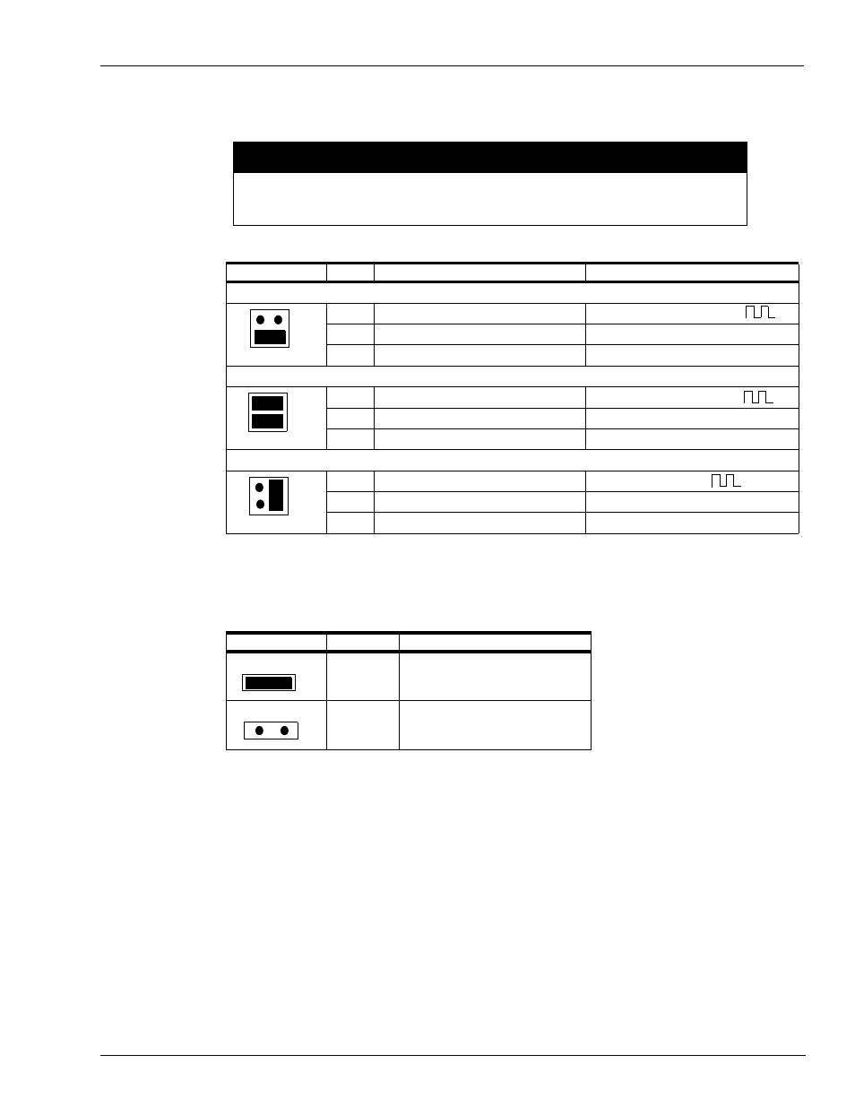
Pulse Connection: Verify that the K1 through K4 jumpers (pulse type jumpers) match the type
pulser being used for each pump position. Use the table below to determine your settings.
4
Debounce Configuration: Verify that the K5 jumper (debounce) is set properly. The K5
jumper should remain jumpered for all Reed switch quantity pulsers and unjumpered for all
electronic and money pulsers.
5
Replace the cover plate on the pump control I/O board and re-install the board into the card
cage.
6
Replace the five green connectors into the proper sockets on the front of the Pump Control I/O
board.
7
Repeat all steps for both the EXPMUX Pump Control CPU and Pump Control I/O PCBs for
each pump control unit.
Jumper
Pin
Function
Voltage
VR Reed Switch Pulser, 1871 Series
P
Pulser signal input (sink)
12 VDC signal when pulsing
+
No connection
G
DC ground for pulser
DC ground
VR Electronic Pulser, 7871 Series
P
Pulser signal input (sink)
12 VDC signal when pulsing
+
+12 VDC supply voltage for pulser
+12 VDC
G
DC ground for pulser
DC ground
VR Totalizer Pulser, 7874 Series
P
Pulser signal input (sink)
Signal when pulsing
+
Voltage for opto-isolator from pulser
Voltage level of pulser
G
DC ground for pulser
DC ground
Jumper
Speed
Function
K5 Jumpered
Slow
10:1 quantity pulsers
K5 Open
Fast
10:1 money pulsers
All electronic pulsers
K1 to K4 jumpers must be set in the configurations shown before turning on power to the
PCU or damage to the system components may occur.
CAUTION
K1
1
2
K1
1
2
K1
1
2