9 – dc power measurement and adjustment, Site controller iii, Pump control unit(s) – Gasboy Site Controller III Start-Up User Manual
Page 73: 5 vdc measurement, Dc power measurement and adjustment, Site controller iii pump control unit(s), Figure 9-1: pcu +5 vdc measurement points
MDE-4375 CFN Series Site Controller III Start-Up Manual · June 2005
Page 61
DC Power Measurement and Adjustment
9 – DC Power Measurement and Adjustment
The following steps describe, for each of the components, how to measure the voltages
required in Section 9. DC POWER of the Start-up form. If any of the measured DC voltages
are outside of the tolerances noted (except for +5 which can be adjusted), immediately shut off
the AC POWER switch of the unit and diagnose the problem. Test points are shown for each
of the system devices in this section. All voltage measurements should be taken with the
negative lead of the digital voltmeter on the ground (GND) test point.
Site Controller III
The Site Controller III has no DC power adjustments.
Pump Control Unit(s)
+5 VDC Measurement
1
Turn off the AC and DC power switches on the supply assembly.
2
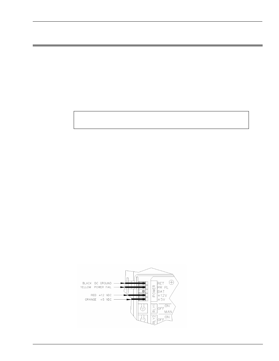
Locate the connector labeled POWER in the upper left-hand corner of the motherboard.
Remove the black plastic cover.
3
Turn on the AC and DC power switches.
4
Measure the +5 VDC between the orange (+) and black (-) wires (
The voltage should be +4.95 to +5.05 VDC.
Figure 9-1: PCU +5 VDC Measurement Points
9. DC POWER
As you are measuring the noted voltages, fill in the readings for each in this section of the Start-up
Form.