Re-install the expmux pump control cpu board – Gasboy Site Controller III Start-Up User Manual
Page 53
MDE-4375 CFN Series Site Controller III Start-Up Manual · June 2005
Page 41
Jumpers & Switch Settings
10
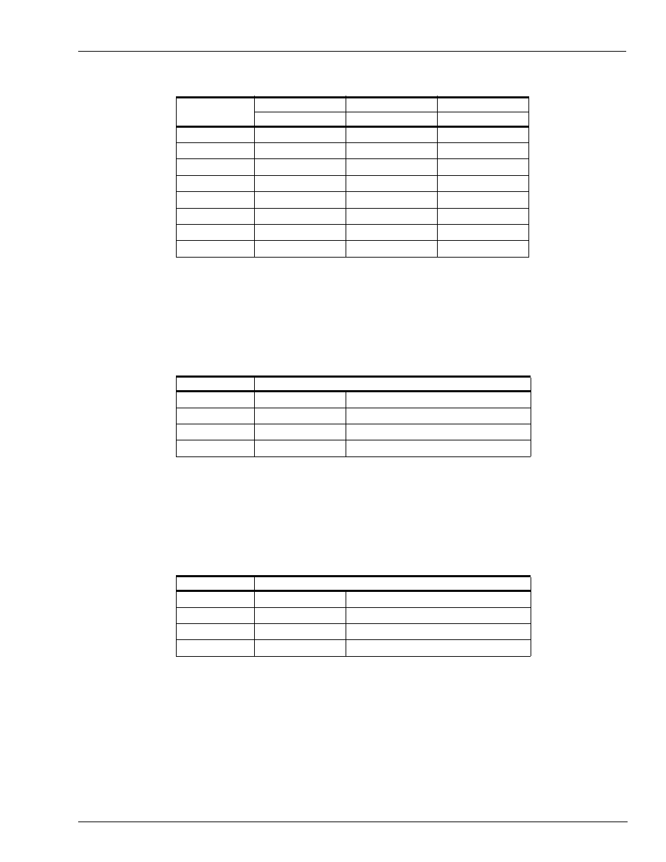
The settings for switch bank SC (1 through 4) determine when the pump control unit begins
counting pulses for a particular pump. When a switch is open, the PCU begins counting pulses
when the corresponding pump is activated. When a switch is closed, as it should be for most
configurations using mechanical pumps, the PCU does not count pulses for the corresponding
pump until the mechanical reset has completed. The switch should be closed when the pump
is wired for postpay-prepay console operations.
11
In switch bank SC, 5 through 8, only switch 6 and 8 are active. Switch SC-6 is the Deadman
Timer Switch. If enabled, the pump control unit must be polled at least every 15 seconds by
the Site Controller. If it fails to sense a poll at that time, it turns all relays off. If Reset
Complete Mode is used on any pump on a particular PCU, the deadman timer should be
disabled. Switch SC-8 enables the test mode allowing the basic PCU functions to be tested
without the use of a site controller.
12
Re-install the EXPMUX Pump Control CPU board.
Delay Time
(seconds)
SB-6
SB-7
SB-8
RLY1
RLY2
RLY3
0
Closed
Closed
Closed
1
Open
Closed
Closed
2
Closed
Open
Closed
3
Open
Open
Closed
4
Closed
Closed
Open
5
Open
Closed
Open
6
Closed
Open
Open
7
Open
Open
Open
Switch
Function
SC-1
Mode pump 1
Open = Normal, Closed = Reset Complete
SC-2
Mode pump 2
Open = Normal, Closed = Reset Complete
SC-3
Mode pump 3
Open = Normal, Closed = Reset Complete
SC-4
Mode pump 4
Open = Normal, Closed = Reset Complete
Switch
Function
SC-5
No function in on-line mode
SC-6
DEAD
Open - deadman timer enabled
SC-7
No function in on-line mode
SC-8
TEST
Open - Test mode; Closed - On-line mode