Pump control expmux cpu board, Figure 5-4: expmux cpu board – Gasboy Site Controller III Start-Up User Manual
Page 51
MDE-4375 CFN Series Site Controller III Start-Up Manual · June 2005
Page 39
Jumpers & Switch Settings
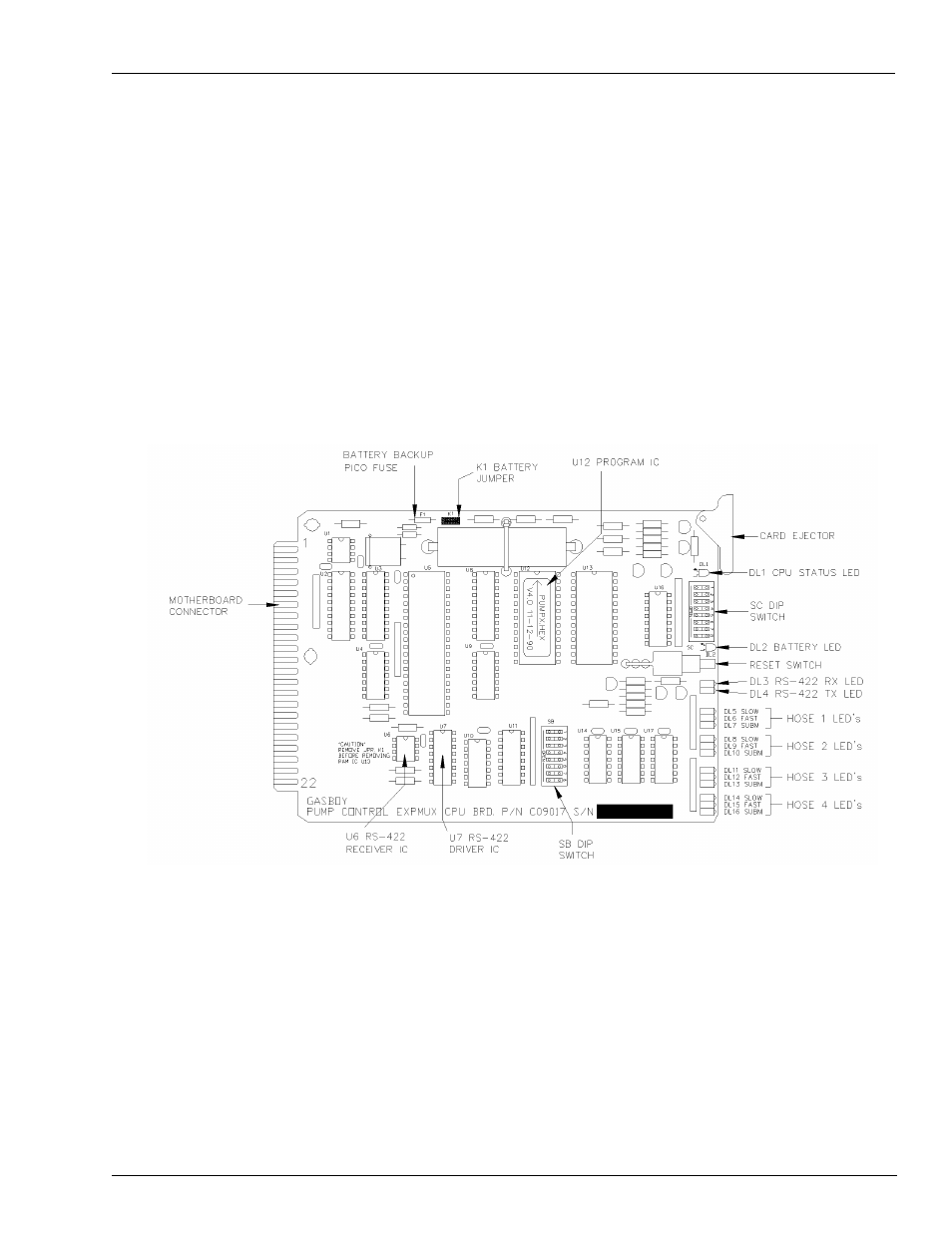
Pump Control EXPMUX CPU Board
1
Unlock and open the front door of the pump control unit.
2
Make sure all override switches are in the AUTO position. See
3
Make sure the AC power and battery switches, located in the upper righthand corner of the
power supply are turned OFF (down).
4
Loosen the screw for the card cage section, and swing out the card cage.
5
Remove the pump control EXPMUX CPU board (
), located in the rear portion of
the card cage, by pulling on the top white tab.
Figure 5-4: EXPMUX CPU Board
6
Locate the K1 jumper patch and install the jumper. This jumper allows battery voltage to the
RAM. It should be installed for normal operation and removed for storage to prevent battery
discharge.
7
Address: Verify that the pump control CPU board switch bank, SB (1 through 4), is set for the
proper address. An address must be set to identify the pump control unit when it is connected
to the CFN System. This address is a unique identifier for multiple PCU’s that are connected
on the same RS-485 line. Addressing should start at 1 and continue sequentially through 16.
The physical wiring order does not have to correspond with the address order, that is, the first
unit on the RS-485 line does not have to be address 1.
Switches 1 through 4 denote the address. This is factory set and may not have to be corrected.