Polarization settings – Basler Electric BE1-11t User Manual
Page 98
86
9424200995 Rev H
Negative-Sequence Polarization is used to test directionally for all fault types except three-phase faults.
Negative-sequence bits are used to supervise phase, neutral, and negative-sequence overcurrent modes.
With load flow and low fault currents, it is possible for the positive-sequence bits to be set at the same
time negative-sequence bits are true. Under these conditions, the negative-sequence bits have priority
and the positive-sequence bits are cleared.
Zero-Sequence Voltage Polarization is used to test directionally for ground faults and is used to supervise
only in neutral overcurrent mode (V0IN, V0IG, VXIN, CXIN, VXIG, or CXIG). The neutral overcurrent
elements can be set to operate on either calculated I
0
or independent ground input I
G
. The four types of
zero-sequence polarization methods were described above. Typical ac connections for external sources
of V
0
(a broken delta VT) are provided in the
chapter.
Zero-Sequence Current Polarization is also used to test directionally for ground faults and is used to
supervise the neutral overcurrent elements.
Polarization summary for tripping elements is as follows:
•
Phase mode: Positive-Sequence; Negative-Sequence
•
Negative-Sequence mode: Negative-Sequence
•
Neutral mode: Negative-Sequence; Zero-Sequence Volt; Zero-Sequence Current
The neutral overcurrent elements can be supervised by various polarization methods using either or both
zero-sequence and negative-sequence quantities. This is necessary depending on the application and
fault conditions applied to the BE1-11t. For example, negative-sequence polarizing can be used when
zero-sequence mutual coupling effects cause zero-sequence polarizing elements to lose directionality. In
addition, high Z ground faults might cause values of zero-sequence voltage too low to measure during a
fault, making zero-sequence polarization unreliable. A similar condition can occur with the negative-
sequence voltage or current, although it is less likely. Under these conditions, a user might need to use
current polarization or dual polarization to provide reliable directional tripping.
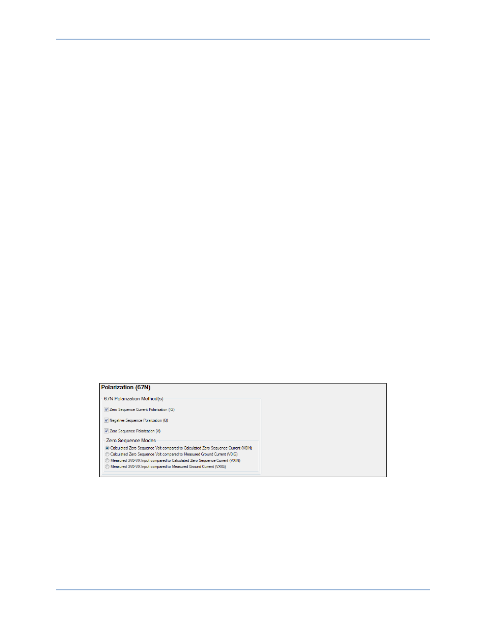
Polarization Settings
Polarization methods are configured on the Polarization (67N) settings screen (Figure 58) in
BESTCOMSPlus. Setting ranges and defaults are summarized in Table 31.
BESTCOMSPlus Navigation Path: Settings Explorer, Protection, Current, Polarization (67N)
HMI Navigation Path: Settings Explorer, Protection, Settings Group x (where x = 0 to 3), Current
Protection, Directional Current 67
Figure 58. Polarization (67N) Settings Screen
Directional Overcurrent (67) Protection
BE1-11t