Logic connections, Figure 65 – Basler Electric BE1-11t User Manual
Page 113
9424200995 Rev H
101
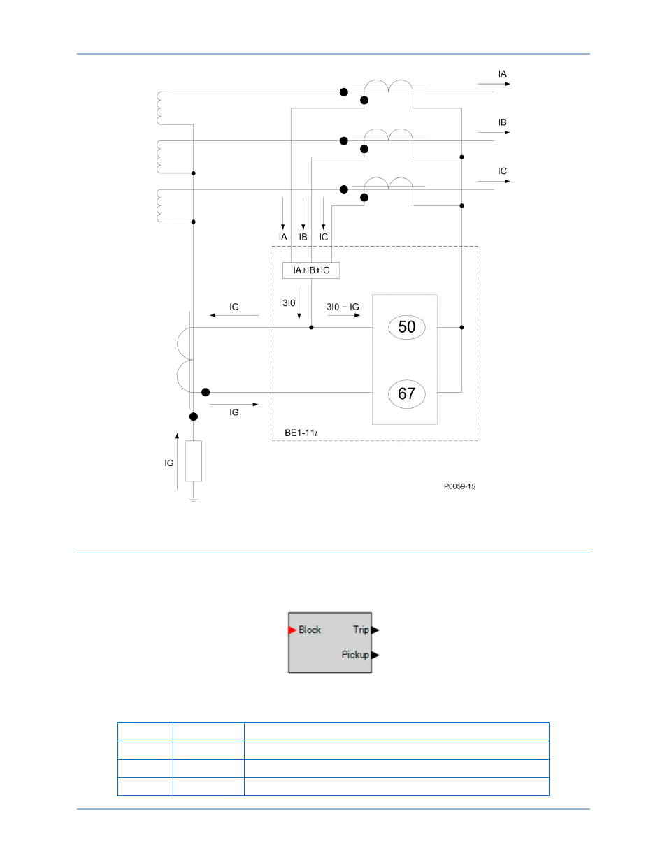
Figure 65. Current-Polarized Directional Scheme for BE1-11t CT Connection
Logic Connections
Neutral current differential element logic connections are made on the BESTlogicPlus screen in
BESTCOMSPlus. The neutral current differential element logic block is illustrated in Figure 66. Logic
inputs and outputs are summarized in Table 36.
Figure 66. Neutral Current Differential Element Logic Block
Table 36. Logic Inputs and Outputs
Name
Function
Purpose
Block
Input
Disables the 87N function when true
Trip
Output
True when the 87N element is in trip condition
Pickup
Output
True when the 87N element is in pickup condition
BE1-11t
Neutral Current Differential (87N) Protection
This manual is related to the following products: