Element blocking, Logic connections, Operational settings – Basler Electric BE1-11t User Manual
Page 61
9424200995 Rev H
49
Element Blocking
Fuse Loss
The fuse loss (60FL) element of the BE1-11t can be used to block 27X protection when fuse loss or loss
of potential is detected in a three-phase system.
If the 60FL element trip logic is true and Block Phase/V1 is enabled, the 27X function will be blocked
when configured for V1 mode. If Block V2 is enabled, the 27X function will be blocked when configured
for V2 mode. If Block 3V0 is enabled, the 27X function will be blocked when configured for 3V0 mode.
See the
chapter for more information on the 60FL function.
Protective elements blocked by 60FL should be set so that trip times are 60 milliseconds or greater to
assure proper coordination of blocking.
Block Logic Input
The Block input provides logic-supervision control of the element. When true, the Block input disables the
element by forcing the Trip and Pickup outputs to logic 0 and resetting the element timer. Connect the
element Block input to the desired logic in BESTlogicPlus. When the element is initially selected from the
Elements view, the default condition of the Block input is a logic 0.
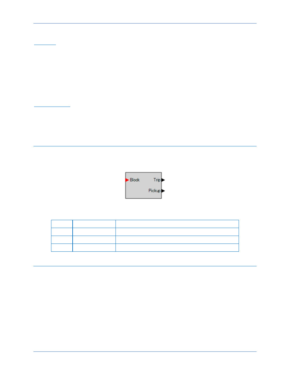
Logic Connections
Auxiliary undervoltage element logic connections are made on the BESTlogicPlus screen in
BESTCOMSPlus. The auxiliary undervoltage element logic block is illustrated in Figure 40. Logic inputs
and outputs are summarized in Table 13.
Figure 40. Auxiliary Undervoltage Element Logic Block
Table 13. Logic Inputs and Outputs
Name
Logic Function
Purpose
Block
Input
Disables the 27X function when true
Trip
Output
True when the 27X element is in a trip condition
Pickup
Output
True when the 27X element is in a pickup condition
Operational Settings
Auxiliary undervoltage element operational settings are configured on the Undervoltage (27X) settings
screen (Figure 41) in BESTCOMSPlus. Setting ranges and defaults are summarized in Table 14.
BE1-11t
Auxiliary Undervoltage (27X) Protection