Programmable alarm, Logic connections, Operational settings – Basler Electric BE1-11t User Manual
Page 201
9424200995 Rev H
189
Programmable Alarm
The BE1-11t indicates an alarm condition when the 60FL element detects a fuse loss or loss of potential.
The alarm appears on the front-panel display, web page interface, and on the Alarms metering screen in
BESTCOMSPlus. Refer to the
chapter for information on how to program alarms.
Logic Connections
Fuse loss logic connections are made on the BESTlogicPlus screen in BESTCOMSPlus. The fuse loss
element logic block is illustrated in Figure 142. The logic output is summarized in Table 73.
Figure 142. Fuse Loss Element Logic Block
Table 73. Logic Output
Name
Logic Function
Purpose
Fuse Loss
Output
True when the 60FL logic is true
Operational Settings
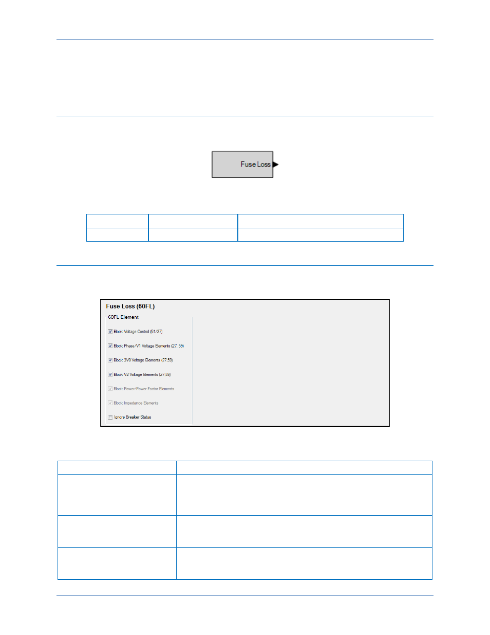
Fuse loss element operational settings are configured on the Fuse Loss (60FL) settings screen
(Figure 143) in BESTCOMSPlus. Settings are summarized in Table 74.
Figure 143. Fuse Loss Settings Screen
Table 74. Operational Settings
Setting
Purpose
Block Voltage Control (51/27)
When enabled and the 60FL logic is true (voltage sensing is lost), the
current tripping level is controlled by the 51 function and the 27R
function is inhibited. When enabled and the 60FL logic is false, the
current tripping level is controlled by the 51/27R function.
Block Phase/V1 Voltage
Elements
All functions that use phase voltage (P) and positive-sequence
voltage (V1) measurements are blocked when the 60FL logic is true.
(27 and 59)
Block 3V0 Voltage Elements
All functions that use the three-phase residual voltage (3V0)
measurement are blocked when the 60FL logic is true. (27X, 59X -
3V0 mode)
BE1-11t
Fuse Loss (60FL)