O figure 113 – Basler Electric BE1-11t User Manual
Page 165
9424200995 Rev H
153
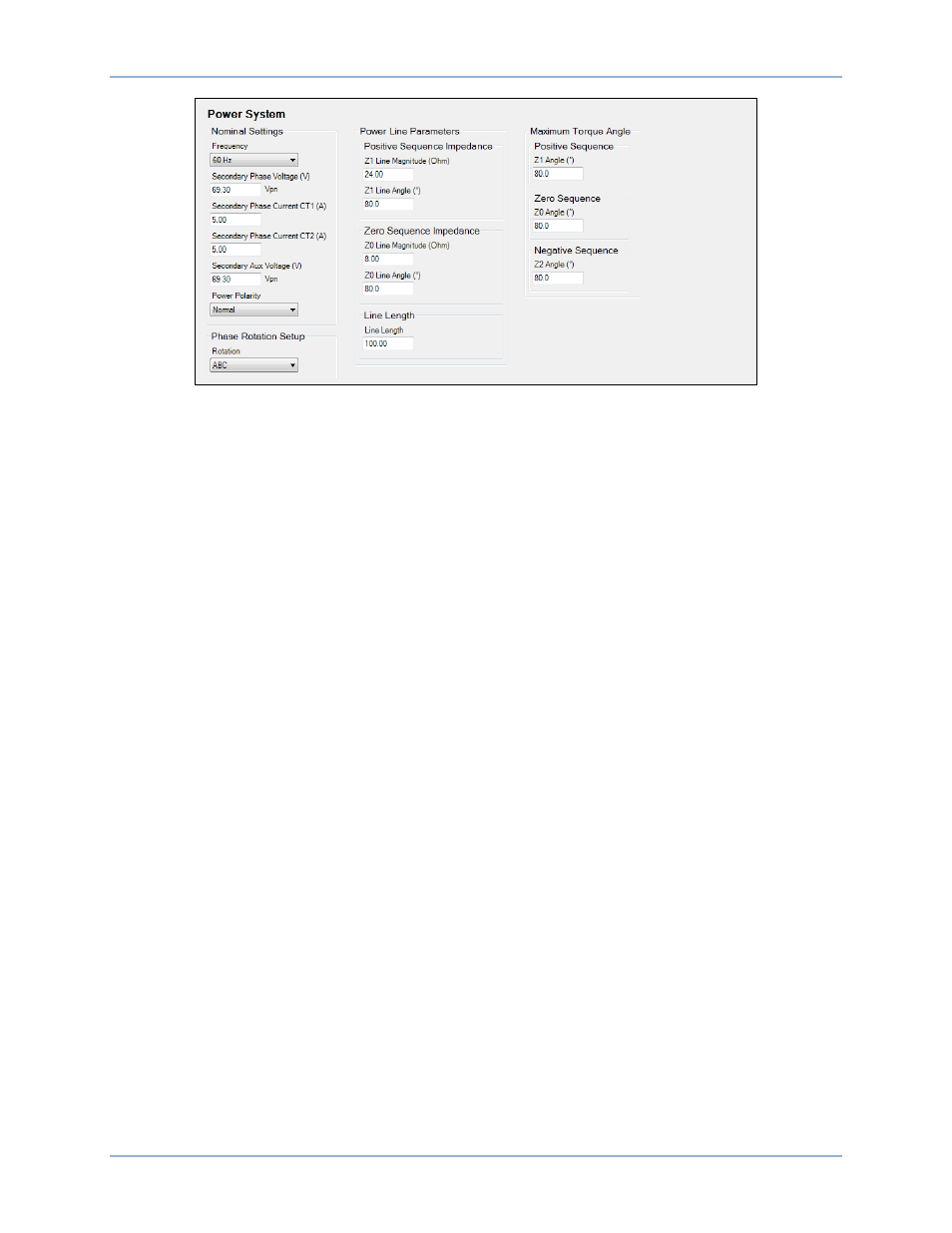
Figure 113. Power System Screen
Note that both Z1-MAG and Z0-MAG are scaled by 10 times to represent the entire length of the power
line. Since the units are in kilometers, the distance results would also be in kilometers.
Distance calculations are performed post-fault using vector data captured during the actual fault. Pre-fault
current vectors are captured three cycles prior to pickup. Fault voltage and current vectors are captured
two cycles after the trip command is issued. The two-cycle wait time allows line transients to settle to
provide results that are more accurate.
To perform the actual distance calculation, the BE1-11t first must determine the faulted phase. Faults can
be categorized depending on the lines faulted. The various categories are LLL, LL, LLG, or LG where L =
line and G = ground.
To determine the faulted phase, the fault vectors are compensated for load flow using the pre-fault data.
Next, the compensated vectors are run through a series of sequence component comparisons. Once the
faulted phase is determined, the fault data along with the line parameters are applied using the Takagi
algorithm to determine the impedance of the faulted line. The impedance is divided by the impedance per
unit length to determine the distance to fault. This method assumes the line is homogenous and that the
line parameters do not change over the length specified. For a non-homogenous line, the distance would
need to be manually corrected.
The distance-to-fault results are limited to
±300% of the specified line length. This limit prevents
erroneous results from being displayed for non-overcurrent type faults, such as over or undervoltage
faults. A computed value greater than maximum line length is reported as n/a (not applicable).
BE1-11t
Fault Reporting