Logic connections, Operational settings – Basler Electric BE1-11t User Manual
Page 76
64
9424200995 Rev H
Logic Connections
Frequency element logic connections are made on the BESTlogicPlus screen in BESTCOMSPlus. The
frequency element logic block is illustrated in Figure 46. Logic inputs and outputs are summarized in
Table 20.
Figure 46. Frequency Element Logic Block
Table 20. Logic Inputs and Outputs
Name
Logic Function
Purpose
Block
Input
Disables the 81 function when true
Trip
Output
True when the 81 element is in a trip condition
Pickup
Output
True when the 81 element is in a pickup condition
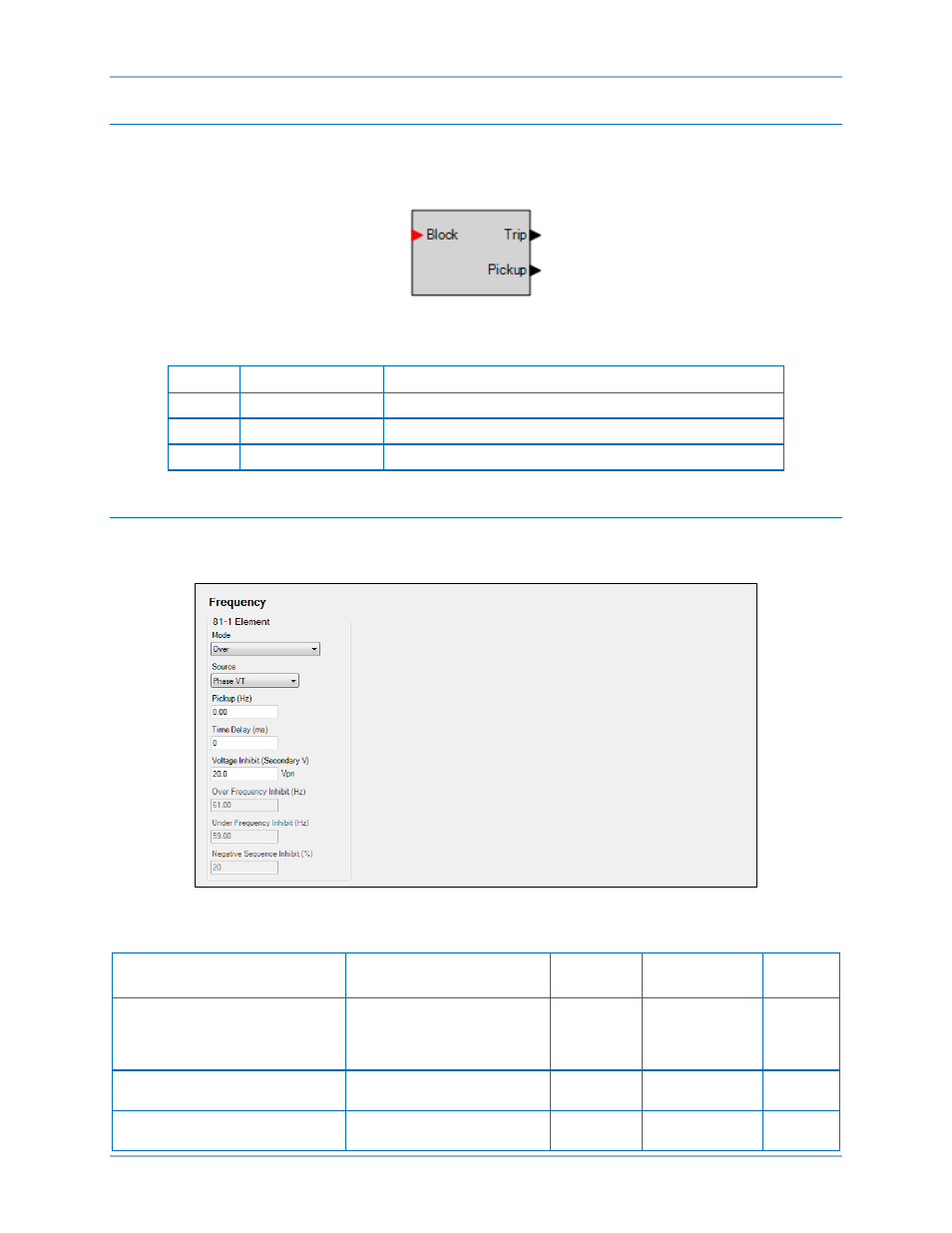
Operational Settings
Frequency element operational settings are configured on the Frequency settings screen (Figure 47) in
BESTCOMSPlus. Setting ranges and defaults are summarized in Table 21.
Figure 47. Frequency Settings Screen
Table 21. Operational Settings
Setting
Range
Increment
Unit of
Measure
Default
Mode
Disabled, Over, Under,
Rate of Change,
Positive Rate of Change,
or Negative Rate of Change
n/a
n/a
Disabled
Source
Phase VT or Aux VT
n/a
n/a
Phase
VT
Pickup
0 or 0.2 to 20 for ROC mode
0 or 15 to 70 for O/U mode
0.01
hertz/sec (ROC)
hertz (O/U)
0
Frequency (81) Protection
BE1-11t