Functional test report, Delay timer verification, Control timer verification – Basler Electric BE1-11t User Manual
Page 390
378
9424200995 Rev H
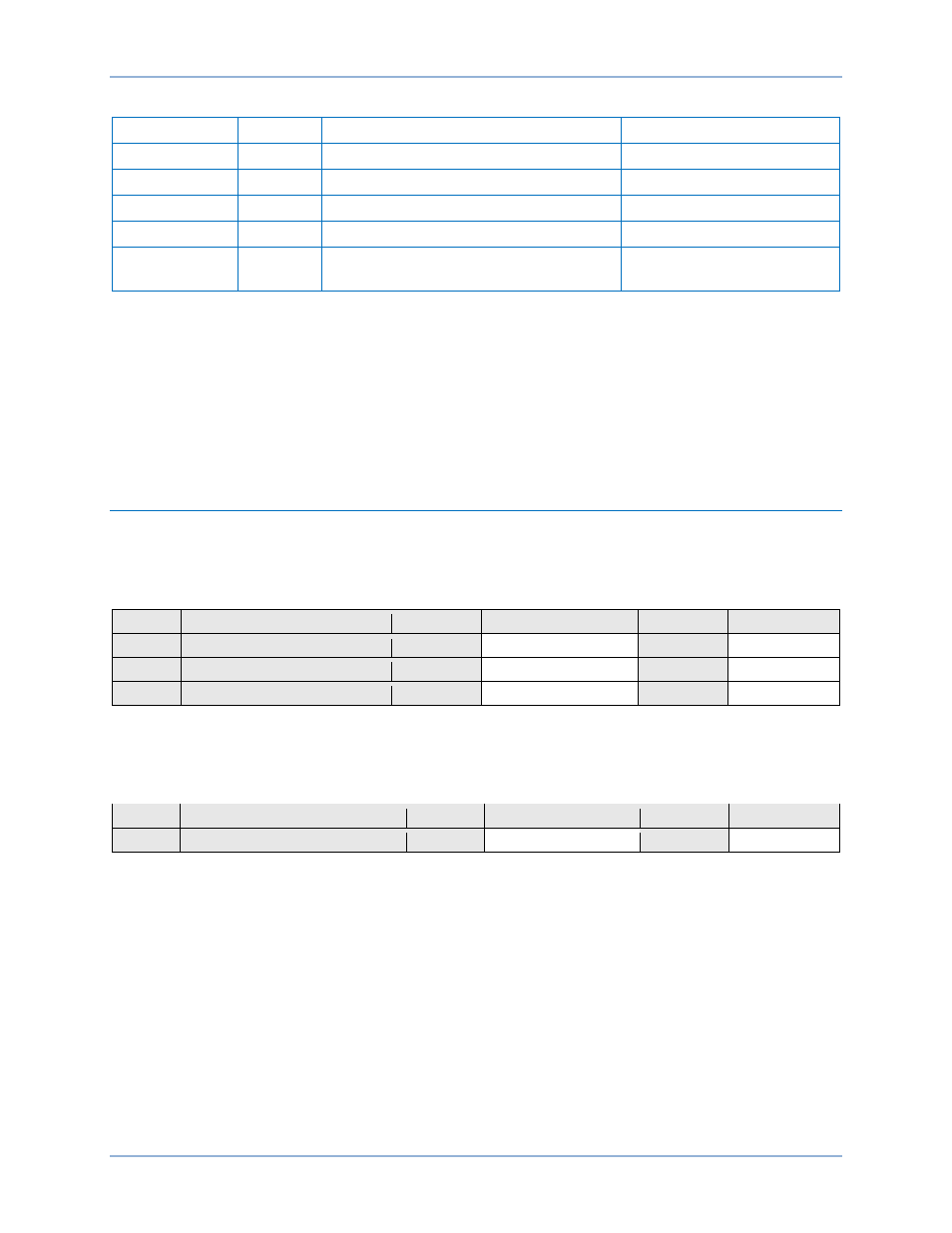
Table 169. Control Time Delay Settings
Setting
Value
BESTCOMSPlus Screen
Description
Phase Pickup
1 A
Protection, Current, Breaker Fail (50BF)
Sets phase pickup to 1 A
Ground Pickup
1 A
Protection, Current, Breaker Fail (50BF)
Sets ground pickup to 1 A
Control Timer
100 ms
Protection, Current, Breaker Fail (50BF)
Sets control timer to 100 ms
Delay Timer
200 ms
Protection, Current, Breaker Fail (50BF)
Sets delay timer to 200 ms
Pickup
2 A
Protection, Current, Instantaneous
Overcurrent (50-1)
Sets pickup to 2 A
Step 12: Connect a current source to terminals D1 and D2 (A-phase). Apply nominal current to the
BE1-11t and note operation of OUT3 and no operation of OUT1 and OUT2. To verify control
time, apply nominal current and start the test set timer. Use OUT3 to stop the timer. Record the
result.
Step 13: (Optional.) Repeat steps 1 through 12 for the B and C phase elements. Note: Set 50-1 mode to
IB for B-phase and IC for C-phase.
Step 14: (Optional.) Repeat steps 7 through 13 with CT Circuit 2 as the source. In step 12, replace D1
with F1, D2 with F2, etc.
Functional Test Report
Delay Timer Verification
Delay Timer Range = 50 to 999 ms
Delay Timer Accuracy =
±0.5% or +1¼, −0.5 cycles, whichever is greater
Step
Delay Timer Setting
Low
Actual Timing
High
Pass/Fail
4
100 ms
92 ms
120 ms
P / F
6
200 ms
192 ms
220 ms
P / F
6
300 ms
292 ms
320 ms
P / F
Control Timer Verification
Control Timer Range = 50 to 99 ms
Control Timer Accuracy =
±0.5% or ½ cycle, whichever is greater
Step
Control Timer Setting
Low
Actual Timing
High
Pass/Fail
12
100 ms
92 ms
120 ms
P / F
Breaker Fail (50BF) Test
BE1-11t