Functional test report, Pickup verification, Timing verification – Basler Electric BE1-11t User Manual
Page 337
9424200995 Rev H
325
Step 2: Prepare to monitor the 27P-1 timings. Timing accuracy is verified by measuring the elapsed
time between a sensing voltage change and OUT1 closing.
Step 3: Connect and apply a 120 Vac, three-phase voltage source to terminals C13 (A-phase), C14 (B-
phase), C15 (C-phase), and C16 (Neutral).
Step 4: Step the A-phase voltage down to 110 volts. Measure the time delay and record the result.
Step 5: Repeat step 4 for the 5,000 ms and 10,000 ms time delays of Table 114. Record the results.
Step 6: (Optional.) Repeat steps 1 through 5 for the B-phase and C-phase voltage inputs. Note: Be sure
to enable proper target for each phase being tested.
Step 7: (Optional.) Repeat steps 1 through 6 through 6 for settings group 1, 2, and 3.
Step 8: (Optional.) Repeat steps 1 through 7 for 27P-2, 27P-3, 27P-4, and 27P-5.
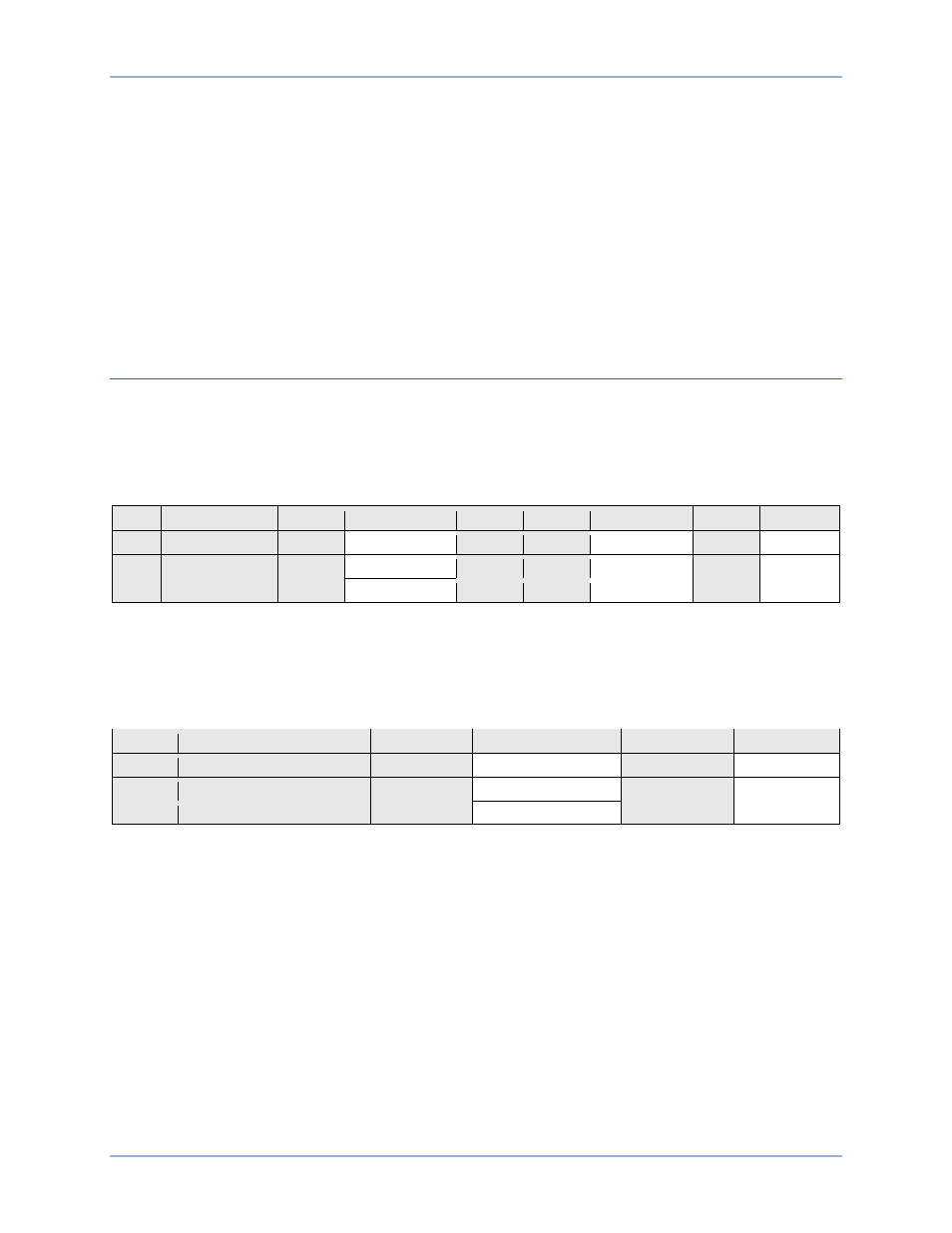
Functional Test Report
Pickup Verification
Pickup Setting Range = 1 to 300 V
Pickup Accuracy =
±2% or ±1 V, whichever is greater
Reset/Pickup Ratio = 102%
±1%
Step
Pickup Setting
Low
Actual Pickup
High
Low
*
Actual Reset
High
*
Pass/Fail
6
235.0 V
230.3 V
239.7 V
237.3 V
242.0 V
P / F
7
115.0 V
112.7 V
117.3 V
116.1 V
118.4 V
P / F
7
65.0 V
63.7 V
61.2 V
65.6 V
66.9 V
P / F
* Reset range is calculated from the pickup setting and may need adjusted based on actual pickup.
Timing Verification
Time Delay Range = 50 to 600,000 ms
Timing Accuracy =
±0.5% or ±2 cycles, whichever is greater
Step
Time Delay Setting
Low
Actual Timing
High
Pass/Fail
4
2,000 ms
1,968 ms
2,032 ms
P / F
5
5,000 ms
4,968 ms
5,032 ms
P / F
5
10,000 ms
9,950 ms
10,050 ms
P / F
BE1-11t
Phase Undervoltage (27P) Test