E figure 135, Ee table 69) – Basler Electric BE1-11t User Manual
Page 194
182
9424200995 Rev H
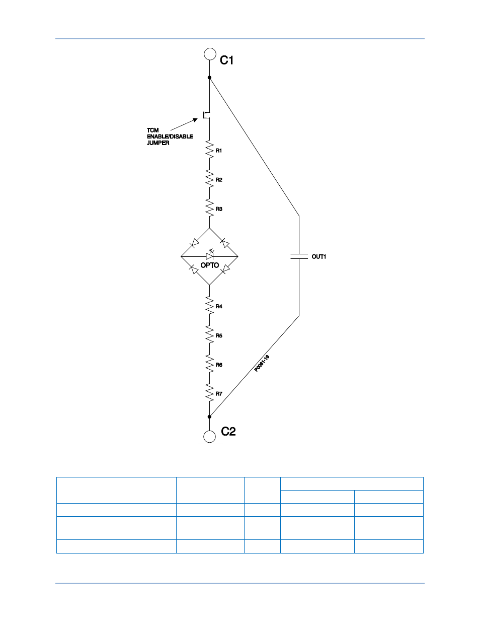
Figure 135. Trip Detector Circuit
Table 69. Current Draw for each Power Supply Voltage Rating
Power Supply Voltage Rating
Resistor
R Total
Optical Isolator
Off (25% V)
On (80% V)
24 Vdc
R1 - R7 = 2.2 k
Ω 15.4 kΩ 6.0 V (0.390 mA)
19.2 V (1.25 mA)
48/125 Vdc
R1 = 6.8 k
Ω
R2 - R7 = 4.7 k
Ω
35 k
Ω
12.0 V (0.343 mA)
38.4 V (1.10 mA)
125/250 Vdc
R1 - R7 = 13 k
Ω
91 k
Ω
31.2 V (0.344 mA)
100 V (1.10 mA)
Figure 136 illustrates typical trip circuit monitor connections for the BE1-11t.
Trip Circuit Monitor (52TCM)
BE1-11t
This manual is related to the following products: