Element blocking, Logic connections, Operational settings – Basler Electric BE1-11t User Manual
Page 66
54
9424200995 Rev H
Trip
The Trip output becomes true if an overvoltage pickup condition persists for the duration of the element
Time Delay setting or calculated inverse time. In BESTlogicPlus, the Trip output can be connected to
other logic elements and to a physical relay output to annunciate the condition and to initiate corrective
action. If a target is enabled for the element, the BE1-11t will record a target when the Trip output
becomes true. See the
chapter for more information about target reporting.
Element Blocking
Fuse Loss
The fuse loss (60FL) element of the BE1-11t can be used to block 59P protection when fuse loss or loss
of potential is detected in a three-phase system.
If the 60FL element trip logic is true and Block Phase/V1 is enabled, all functions that use the phase
voltage are blocked. See the
chapter for more information on the 60FL function.
Protective elements blocked by 60FL should be set so that trip times are 60 milliseconds or greater to
assure proper coordination of blocking.
Block Logic Input
The Block input provides logic-supervision control of the element. When true, the Block input disables the
element by forcing the Trip and Pickup outputs to logic 0 and resetting the element timer. Connect the
element Block input to the desired logic in BESTlogicPlus. When the element is initially selected from the
Elements view, the default condition of the Block input is a logic 0.
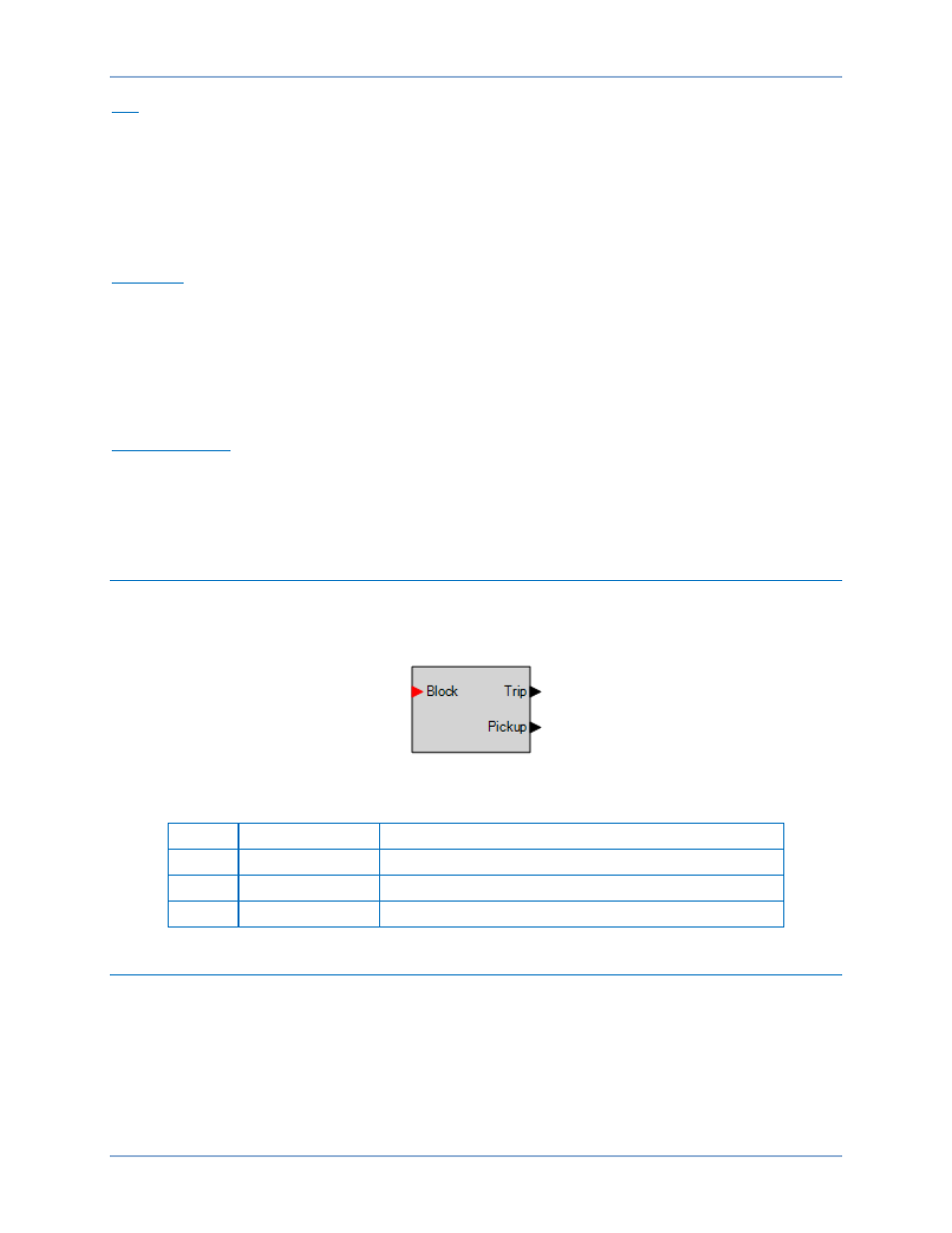
Logic Connections
Overvoltage element logic connections are made on the BESTlogicPlus screen in BESTCOMSPlus. The
overvoltage element logic block is illustrated in Figure 42. Logic inputs and outputs are summarized in
Table 15.
Figure 42. Overvoltage Element Logic Block
Table 15. Logic Inputs and Outputs
Name
Logic Function
Purpose
Block
Input
Disables the 59P function when true
Trip
Output
True when the 59P element is in a trip condition
Pickup
Output
True when the 59P element is in a pickup condition
Operational Settings
Overvoltage element operational settings are configured on the Overvoltage settings screen (Figure 43) in
BESTCOMSPlus. Setting ranges and defaults are summarized in Table 16.
Phase Overvoltage (59P) Protection
BE1-11t