Coordination settings, Figure 49 – Basler Electric BE1-11t User Manual
Page 80
68
9424200995 Rev H
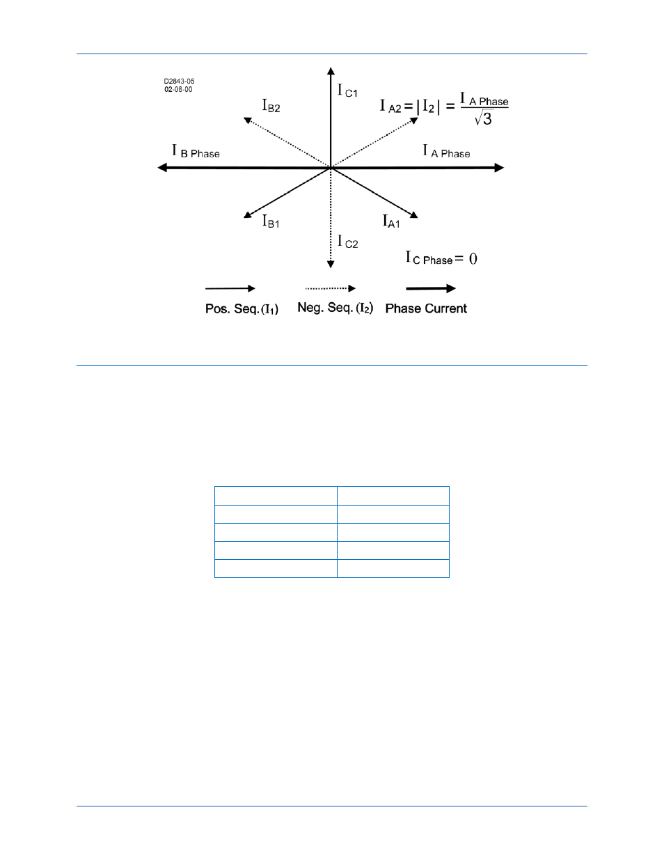
Figure 49. Sequence Components for an A-B Fault
Coordination Settings
The 51-x negative-sequence settings should be checked for coordination with phase-only sensing devices
such as downstream fuses and reclosers and/or ground relays. To plot the negative-sequence time
current characteristics on the same plot for the phase devices, you need to multiply the negative-
sequence element pickup value by the correct multiplier. The multiplier is the ratio of phase current to
negative-sequence current for the fault type for which you are interested. To plot the negative-sequence
time current characteristics on the same plot for the ground devices, you need to multiply the pickup value
by the multiplier for phase-to-ground faults (see Table 22).
Table 22. Fault Type Multipliers
Fault Type
Multiplier
Ph-Ph
m = 1.732
Ph-Ph-G
m > 1.732
Ph-G
m = 3
three-phase
m = infinity
For example, a downstream phase 51-x element has a pickup of 150 amperes. The upstream 51-x
negative-sequence element has a pickup of 200 amperes. To check the coordination between these two
elements for a phase-to-phase fault, the phase overcurrent element would be plotted normally with pickup
at 150 amperes. The 51-x negative-sequence element would be shifted to the right by the appropriate
factor m. Thus, the characteristic would be plotted on the coordination graph with pickup at: (200
amperes)
∗ 1.732 = 346 amperes.
Generally, for coordination with downstream phase overcurrent devices, phase-to-phase faults are the
most critical to consider. All other fault types result in an equal or greater shift of the time current
characteristic curve to the right on the plot.
Negative-Sequence Overcurrent (46) Protection
BE1-11t