Element blocking, Logic connections, Operational settings – Basler Electric BE1-11t User Manual
Page 204
192
9424200995 Rev H
Alarms metering screen in BESTCOMSPlus. Refer to the
chapter for information on how to
program alarms.
The alarm count can be preset and reset through the front-panel interface or BESTCOMSPlus.
Element Blocking
This input allows for logic supervision or control of the element.
The transformer monitor element has a Block logic input which when true, disables the element by forcing
the element Trip and Pickup outputs to logic 0 and resetting the element timer. An element Block input is
connected to the desired logic in BESTlogicPlus.
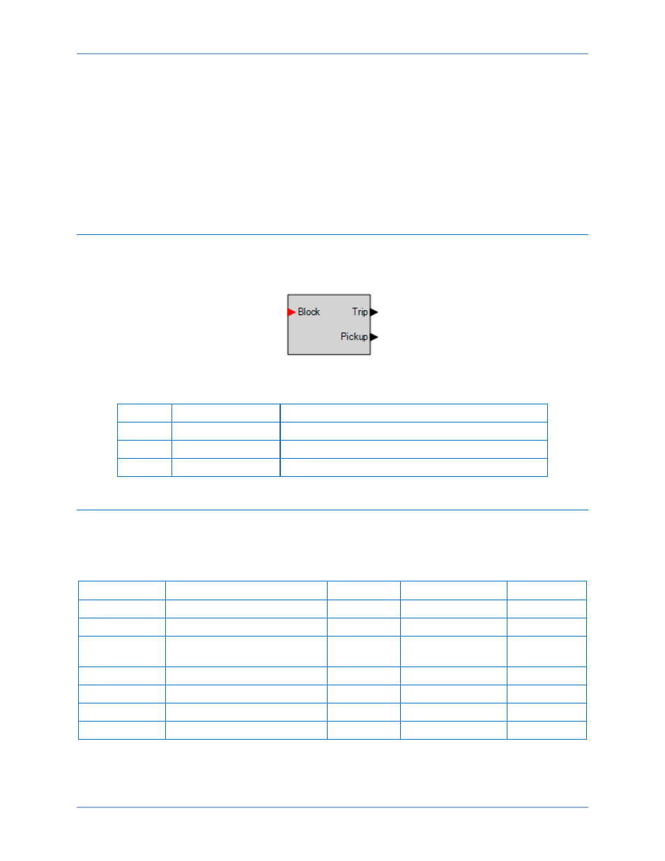
Logic Connections
Transformer monitor element logic connections are made on the BESTlogicPlus screen in
BESTCOMSPlus. The transformer monitor element logic block is illustrated in Figure 144. Logic inputs
and outputs are summarized in Table 75.
Figure 144. Transformer Monitor Element Logic Block
Table 75. Logic Inputs and Outputs
Name
Logic Function
Purpose
Block
Input
Disables the 51TF function when true
Trip
Output
True when the 51TF is in a trip condition
Pickup
Output
True when the 51TF is in a pickup condition
Operational Settings
Transformer monitor element operational settings are configured on the Transformer Monitor (51TF)
settings screen (Figure 145) in BESTCOMSPlus. Setting ranges and defaults are summarized in Table
76.
Table 76. Transformer Monitor (51TF) Settings
Setting
Range
Increment
Unit of Measure
Default
Mode
Enabled or Disabled
n/a
n/a
Disabled
Source
CT Circuit 1 or CT Circuit 2
n/a
n/a
CT Circuit 1
Base Current
0 or 0.5 to 16 (5A CT)
0 or 0.1 to 3.2 (1A CT)
0.001
amps
0
Alarm Count
0 or 1 to 99
1
units
1
Threshold
0 or 1 to 40
0.01
units
2
N Constant
0.5 to 3
0.01
units
2
K Constant
1 to 3,000
0.01
units
1,250
Transformer Monitor (51TF)
BE1-11t