Analog metering functions, Auto ranging, Voltage - primary and secondary – Basler Electric BE1-11t User Manual
Page 148
136
9424200995 Rev H
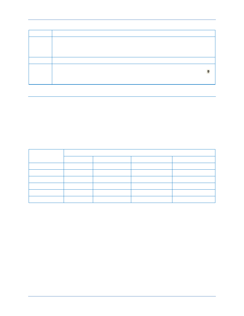
Table 53. Explanation of Figure 95 Call-Outs
Call-Out
Explanation
A
Holding the left mouse button down on a metering tab and dragging it to one of the four
arrow boxes will place it inside the selected window on the location selected. To place the
metering tab as a tab inside the selected window, drop it on the tabs button in the center
of the arrow buttons.
B
This blue transparent square represents the screen being moved.
C
Holding the left mouse button down on a metering tab and dragging it to the right, down,
left, or up arrow box will place it across the side/bottom/top of the screen. Click on the
(thumbtack) to dock it on the side bar. To display a screen that is docked, simply use the
mouse to hover the pointer over the tab on the side bar.
Analog Metering Functions
BE1-11t analog metering functions include voltage, frequency, current, power, differential, and energy.
Metered values are viewed through the Metering Explorer in BESTCOMSPlus, the front-panel display, or
the web page interface on Ethernet equipped protection systems. Refer to the
chapter for
more information. Metering functions are summarized in the following paragraphs. For information on
power, VA, and var calculations, refer to the
chapter.
Auto Ranging
The BE1-11t automatically scales metered values. Table 54 illustrates the ranges for each value metered.
Table 54. Auto Ranging Scales for Metered Values
Metered Value
Unit Display Ranges
Whole Units
Kilo Units
Mega Units
Giga Units
Current
0 A to 999 A
10 kA to 999 kA
1 MA
n/a
Voltage
0 V to 999 V
0 kV to 999 kV
n/a
n/a
Apparent Power
n/a
0 kVA to 999 kVA
1 MVA to 999 MVA
1 GVA to 1000 GVA
Reactive Power
n/a
0 kvar to 999 kvar
1 Mvar to 999 Mvar
1 Gvar to 1000 Gvar
Real Power
n/a
0 kW to 999 kW
1 MW to 999 MW
1 GW to 1000 GW
Frequency
10 to 125 Hz
n/a
n/a
n/a
Voltage - Primary and Secondary
The BE1-11t meters primary and secondary phase-to-neutral voltages (VA, VB, VC), phase-to-phase
voltages (VAB, VBC, VCA), positive-sequence voltage (V1), negative-sequence voltage (V2), neutral-shift
voltage (3V0), auxiliary voltage (Vx), and 3
rd
harmonic auxiliary voltage (Vx 3
rd
Harmonic). The Phase VT
connection determines what is measured. The auxiliary voltage input is user selectable. Refer to the
chapter for more information on configuring Phase VT and AUX VT.
Primary and secondary voltage metering data is found in BESTCOMSPlus (Figure 96) and on the
Metering > Analog Metering > Voltage screen of the front-panel display. A phasor diagram is also
provided in BESTCOMSPlus.
Metering
BE1-11t