Latched mode – Basler Electric BE1-11t User Manual
Page 441
9424200995 Rev H
429
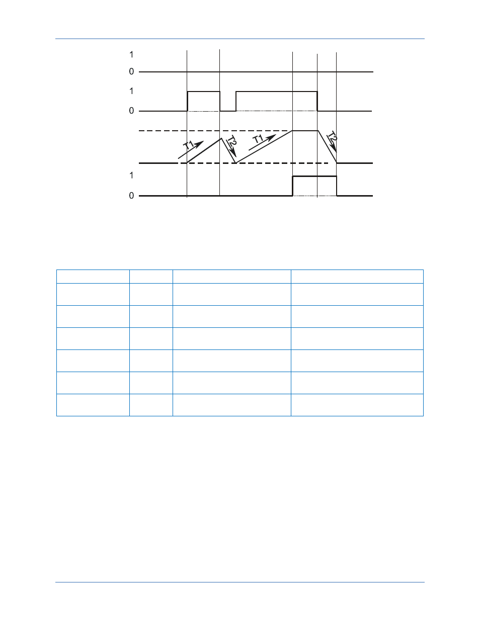
Figure 275. Integrating Timer Mode
Latched Mode
Step 1: Use BESTCOMSPlus to send the operational settings in Table 201 to the BE1-11t. Retain the
logic settings from Figure 270.
Table 201. Operational Settings (Latched Mode)
Setting
Value
BESTCOMSPlus Screen
Description
62-1 Mode
Latched
Control, Logic Timers (62)
Sets 62-1 to One-
Shot/Retriggerable mode
62-1 Time Delay
1 (T1)
30,000
ms
Control, Logic Timers (62)
Sets 62-1 pickup time delay to
15,000 ms
62-1 Time Delay
2 (T2)
0
Control, Logic Timers (62)
Sets 62-1 dropout time delay to 0
43-1 Mode
Pulse
Control, Virtual Control
Switches (43)
Sets 43-1 to Pulse mode
43-2 Mode
Pulse
Control, Virtual Control
Switches (43)
Sets 43-2 to Pulse mode
62-1 Target
Enabled
Target Configuration, Targets
screen.
Enables 62-1 target
Step 2: Use BESTCOMSPlus to configure the BESTlogicPlus programmable logic shown in Figure 276.
•
62-1 initiates when 43-1 output is true.
•
62-1 is blocked when 43-2 output is true.
•
OUT1 closes when 62-1 output is true.
Step 3: Step 5 supplies the 62-1 timer with a latch input by pulsing the 43-1 switch from an OFF state to
an ON state and then back to an OFF state. These commands also supply a block input when
the 43-2 is ON. You can view the state changes of the 43-1 switch at the Metering > Control >
Virtual Switches screen on the front-panel display.
Step 4: Close communication with BESTCOMSPlus.
P
0
0
3
5
-3
4
0
2
-2
7
-0
6
62-x
Block
Initiate
100%
0%
Timer
BE1-11t
Logic Timers (62) Test