Settings example, Een (figure 34), N table 9 – Basler Electric BE1-11t User Manual
Page 52
40
9424200995 Rev H
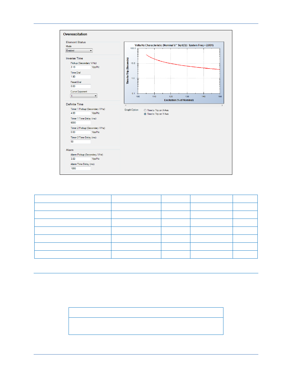
Figure 34. Overexcitation Settings Screen
Table 9. Operational Settings
Setting
Range
Increment
Unit of Measure
Default
Mode
Disabled or Enabled
n/a
n/a
Disabled
Pickup (Inverse Time)
0 or 0.5 to 6
0.01
v/Hz
0
Time Dial (Inverse Time)
0 to 9.9
0.1
units
0
Reset Dial (Inverse Time)
0 to 9.9
0.1
units
0
Curve Exponent (Inverse Time)
0.5, 1, or 2
n/a
n/a
1
Pickup (Definite Time 1 & 2)
0 or 0.5 to 6
0.01
v/Hz
0
Time Delay (Definite Time 1 & 2)
50 to 600,000
varies
milliseconds
50
Settings Example
The overexcitation element is used to de-energize a generator or transformer that is experiencing an
overexcitation condition. Therefore, the manufacturer's overexcitation limit curves are required to
establish optimum protection. Figure 35 and Figure 36 show examples of a transformer and generator
limit curve along with the optimum composite protection characteristic.
Note
Actual damage curves must be obtained from the equipment
manufacturer for the particular equipment to be protected.
Overexcitation (24) Protection
BE1-11t