Logic schemes – Basler Electric BE1-11t User Manual
Page 257
9424200995 Rev H
245
Name
Description
Symbol
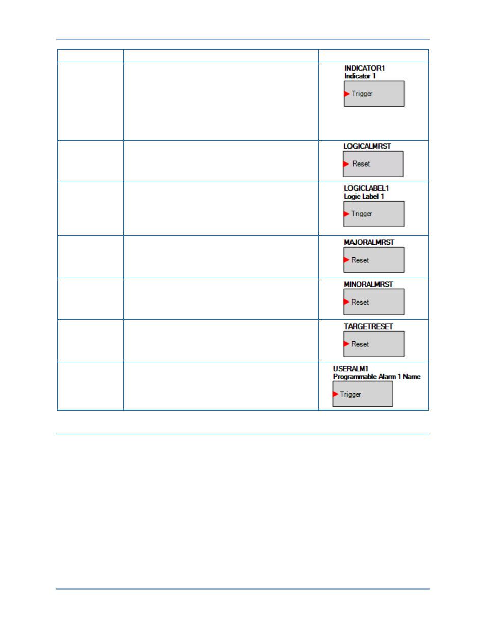
INDICATORx
Indicators 1 through 7.
Refer to the
chapter.
The indicator is displayed in the sequence of events and
the corresponding indicator on the front panel is lit when
the Trigger input is true.
To name indicators, use the Settings Explorer in
BESTCOMSPlus to expand the BESTlogicPlus
Programmable Logic tree branch and select Front Panel
Indicator Labels.
LOGICALMRST
Logic Alarm Reset.
Refer to the
chapter.
LOGICLABELx
Logic Label 1 through 12.
The logic label is displayed in the sequence of events
when the Trigger input is true.
To name logic labels, use the Settings Explorer in
BESTCOMSPlus to expand the BESTlogicPlus
Programmable Logic tree branch and select Logic Labels.
MAJORALMRST
Major Alarm Reset.
Refer to the
chapter.
MINORALMRST
Minor Alarm Reset.
Refer to the
chapter.
TARGETRESET
Target Reset.
Refer to the
USERALARMx
User Alarms 1 through 16.
Refer to the
chapter.
Logic Schemes
A logic scheme is a group of logic variables that defines the operation of a BE1-11t. Each logic scheme is
given a unique name. This gives you the ability to select a specific scheme and be confident that the
selected scheme is in operation. One logic scheme is configured for typical control applications and is the
default active logic scheme. Only one logic scheme can be active at a given time. In most applications,
preprogrammed logic schemes eliminate the need for custom programming. Preprogrammed logic
schemes can provide more inputs, outputs, or features than are needed for a particular application. This
is because a preprogrammed scheme is designed for a large number of applications with no special
programming required. Unneeded logic block outputs can be left open to disable a function or a function
block can be disabled through operating settings.
When a custom logic scheme is required, programming time is reduced by modifying the default logic
scheme.
BE1-11t
BESTlogic
™Plus