Retrieving oscillographic records, Distance to fault, O table 57 – Basler Electric BE1-11t User Manual
Page 164: N figure 112
152
9424200995 Rev H
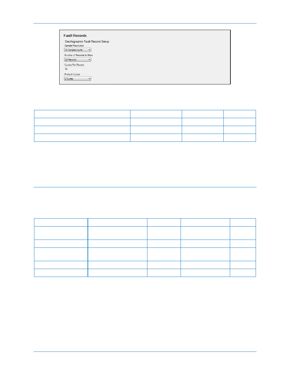
Figure 112. Fault Records Screen
Table 57 summarizes the oscillographic records settings.
Table 57. Oscillographic Records Settings
Setting
Range
Increment
Default
Sample Resolution
32, 16, or 8
n/a
32
Number of Records to Store
32, 16, 8, or 4
n/a
32
Prefault Cycles
0 to 16
1
2
Retrieving Oscillographic Records
Oscillographic records can be downloaded through the Reports, Fault Reports screen in BESTCOMSPlus
(Figure 111). See Fault Reports earlier in this chapter. Oscillographic records can also be downloaded
through the web page interface. For more information, refer to the
chapter.
Distance to Fault
The BE1-11t calculates distance to fault each time a fault record is triggered. Distance to fault is
calculated and displayed based on the power line parameters entered using BESTCOMSPlus or the front-
panel interface. Table 58 provides the power line operating settings.
Table 58. Power Line Operating Settings
Setting
Range
Increment
Unit of Measure
Default
Z1 Line Magnitude
0.05 to 200 (5A CTs)
0.01 to 40 (1A CTs)
varies
ohms
24
Z1 Line Angle
0 to 90
1
degrees
80
Z0 Line Magnitude
0.05 to 650 (5A CTs)
0.01 to 130 (1A CTs)
varies
ohms
8
Z0 Line Angle
0 to 90
1
degrees
80
Line Length
0.01 to 130
0.01
units
100
Line Length describes the power line parameters for which distance is to be computed over. The
parameters should be entered in units per line length with line length being the actual length of the power
line. Line length is entered as unit-less quantities and, therefore, can be entered in kilometers or miles.
Therefore, the distance results would be in whatever units the line length represented.
Using the Settings Explorer in BESTCOMSPlus, power line parameters can be entered on the System
Parameters, Power System screen. Settings are provided for Positive-Sequence Impedance, Zero-
Sequence Impedance, and Line Length. Refer to Figure 113.
Fault Reporting
BE1-11t