Altera DDR SDRAM Controller User Manual
Page 87
A–9
Resynchronization
© March 2009
Altera Corporation
DDR and DDR2 SDRAM Controller Compiler User Guide
shows the manual resynchronization parameters.
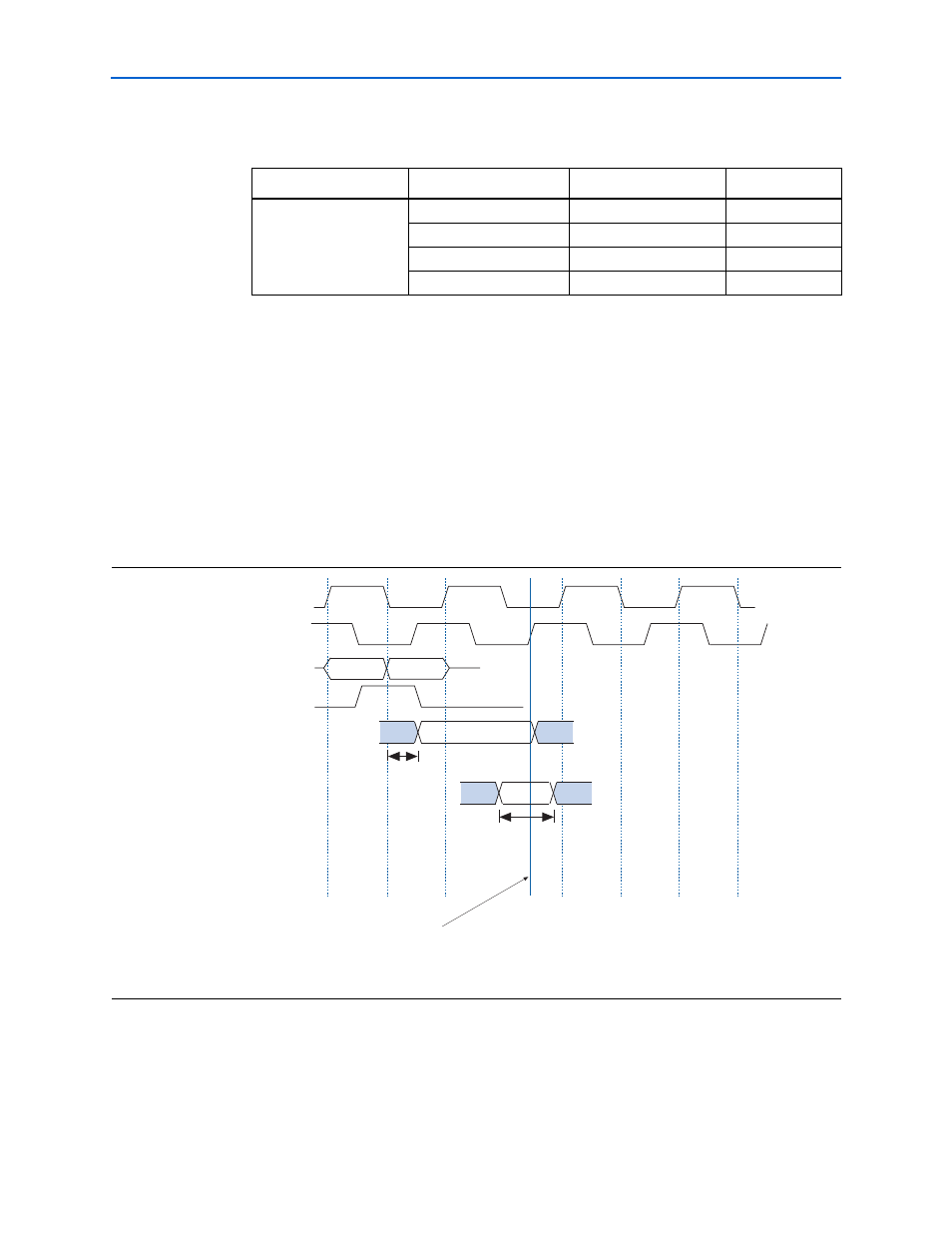
shows an example of how to choose the best manual
resynchronization phase. In this example the best resynchronization phase is cycle =
0, phase = 270
° , and the rising edge of write_clk.
This example is for CAS latency = 2. For CAS latency = 2.5, add 180
° to the
resynchronization phase; for CAS latency = 3, add 1 cycle to the resynchronization
cycle.
Table A–5. Manual Resynchronization Parameters
Cycle
Clock
Edge
Phase (
° )
0, 1, 2, 3, 4, 5, 6
clk
Rising
write_clk
Falling
90
clk
Falling
180
write_clk
Rising
270
Notes to
(1) Resynchronization cycle 0 phase 0 is defined as the first rising edge of clk capable of
resynchronizing the read data for CAS latency = 2.
(2) Use the intermediate resynchronization option to guarantee timing between the
resynchronization registers and registers on the system clock.
Figure A–5. Choosing the Best Resynchronization Phase
Note to
(1)
,
show these registers.
clk
H
L
0
0
1
2
270
0
180
write_clk
Theoretical Q Output
of DQ Capture Register
(see
Note 1)
Actual Data Valid at
D Input of Resynchronization
Register (see
Note 1)
dq
dqs (90 shifted)
Resynchronization
Phase
Resynchronization
Cycle
o
H/L
H/L
Theoretical Round Trip Delay
Safe Resynchronization Window
Best Resynchronization Phase