Compile the example design, Compile the example design –22, Edit the pll” on – Altera DDR SDRAM Controller User Manual
Page 32
2–22
Chapter 2: Getting Started
MegaWizard Plug-In Manager Design Flow
DDR and DDR2 SDRAM Controller Compiler User Guide
© March 2009
Altera Corporation
2. Launch your simulation tool inside this directory and create the following
libraries:
■
<device name>_ver
■
auk_ddr_user_lib
3. Compile the files in
into the appropriate library.
4. Set the Tcl variable gRTL_DELAYS to 0, which tells the testbench not to use the
insert extra delays in the system, because these are applied inside the gate level
model. Configure your simulator to use transport delays, a timestep of
picoseconds, and to include the <device name>_ver library.
Compile the Example Design
You can now edit the PLL(s) and use the Quartus II software to compile the example
design and perform post-compilation timing analysis.
Edit the PLL
The IP Toolbench-generated example design includes a PLL, which has an input to
output clock ratio of 1:1 and a clock frequency that you entered in IP Toolbench. In
addition, IP Toolbench correctly sets all the phase offsets of all the relevant clock
outputs for your design. You can edit the PLL input clock to make it conform to your
system requirements. If you re-run IP Toolbench, it does not overwrite this PLL, if
you turn off Automatically generate the PLL, so your edits are not lost.
1
If you turn on Use fed-back clock, IP Toolbench generates a second PLL—the fed-back
PLL. You need not edit the fed-back PLL.
1
If you change the clock input frequency on the PLL, you must change the
REF_CLOCK_TICK_IN_PS
parameter in the <project name>_tb.v or .vhd file.
f
For more information on the PLL, refer to
“PLL Configurations” on page 3–13
To edit the example PLL, follow these steps:
1. Choose MegaWizard Plug-In Manager (Tools menu).
2. Select Edit an existing custom megafunction variation and click Next.
3. In your Quartus II project directory, for VHDL choose ddr_pll_
for Verilog HDL choose ddr_pll_
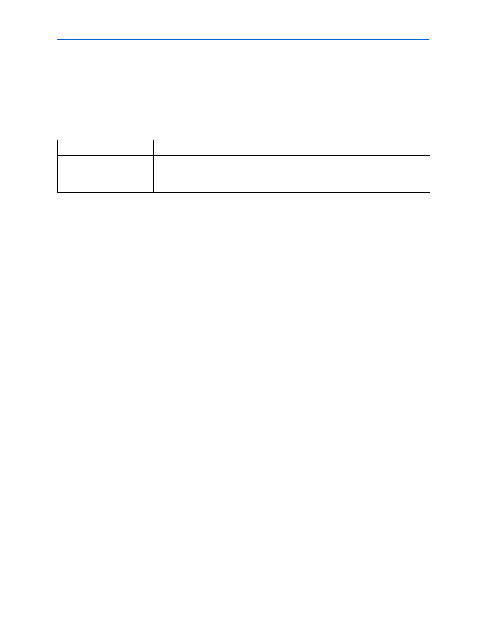
Table 2–5. Files to Compile—Verilog HDL Gate-Level Simulations
Library
Filename
<device name>_ver
<QUARTUS ROOTDIR>/eda/sim_lib/<device name>_atoms.v
auk_ddr_user_lib
<project directory>/testbench/simulation/<simulator name>/
<project directory>/testbench/<testbench name>.v
Notes to
(1) If you are simulating the slow or fast model., the .vho file has a suffix _min or _max added to it. Compile whichever file is appropriate. The
Quartus II software creates models for the simulator you have defined in a directory simulation/<simulator name> in your <project name>
directory..