Board timings, Board timings –39 – Altera DDR SDRAM Controller User Manual
Page 75
Chapter 3: Functional Description
3–39
Parameters
© March 2009
Altera Corporation
DDR and DDR2 SDRAM Controller Compiler User Guide
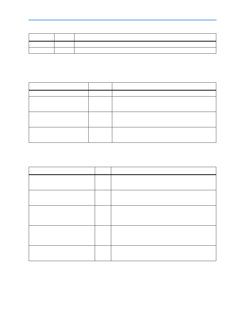
Board Timings
shows the pin loading parameters.
shows the board trace delay parameters. IP Toolbench uses these values to
perform timing analysis.
t
DQSS
cycle
The minimum write command to first DQS latching transition.
t
DQSS
cycle
The maximum write command to first DQS latching transition.
Table 3–19. Device Datasheet Settings (Part 2 of 2)
Parameter
Units
Description
Table 3–20. Pin Loading
Parameter
Units
Description
Manual pin load control
On or off
Turn on or turn off the manual pin load control.
Pin loading on FPGA DQ/DQS pins
pF
The default capacitive loading on the FPGA DQ/DQS pins is based
on the chosen memory type. You should update this figure if it does
not match your board and memory devices.
Pin loading on FPGA
address/command pins
pF
The default capacitive loading on the FPGA address/command pins
is based on the chosen memory type. You should update this figure
if it does not match your board and memory devices.
Pin loading on FPGA clock pins
pF
The default capacitive loading on the FPGA clock pins is based on
the chosen memory type. You should update this figure if it does
not match your board and memory devices.
Table 3–21. Board Trace Delays
Parameter
Units
Description
FPGA clock output to memory chip clock
input, nominal delay
ps
The nominal or average value of the delay attributable to the board
traces from the FPGA clock output pin to the memory device clock
input pin.
Memory DQ/DQS outputs to FPGA inputs,
nominal delay
ps
The nominal or average value of the delay attributable to the board
traces from the memory device DQS and DQ clock output pins to the
FPGA input pins in read mode.
Fed-back clock trace, nominal delay
ps
The nominal or average value of the delay attributable to the board
traces from the FPGA clock output pin to the fed-back clock input
pin. This delay should match the sum of the clock and DQ/DQS trace
lengths.
Tolerance on nominal board delays ±
%
The tolerance on the nominal board trace delays. This tolerance
should take into account any variability between individual boards,
due to temperature or voltage, and different trace lengths to different
memory devices in your system.
Worst trace skew between DQS/DQ/DM in
any one data group
ps
The worst case skew with respect to DQS and any other DQ or DM
signal in any one byte group between any one memory device and
the FPGA.