Controller, Controller –33, Controller ” on – Altera DDR SDRAM Controller User Manual
Page 69
Chapter 3: Functional Description
3–33
Parameters
© March 2009
Altera Corporation
DDR and DDR2 SDRAM Controller Compiler User Guide
Controller
shows the local interface options.
DQ bits per DQS pin
8
Bits
The number of data (DQ) bits for each data strobe (DQS) pin. This
option depend on the type of memory selected. Memories either
support ×4 or ×8 mode. Stratix II and Stratix III devices support
both modes. Cyclone III devices do not support the DQS mode, as
the devices do not have the DQS-related circuitry.
Use ×4 floorplan files that
include DM pins
—
—
Two sets of recommended pins are provided for use with ×4
mode (four DQ per DQS) on the sides of Stratix II devices. If you
do not intend to use the memory DM pins, turn off this control to
give more available pins for your DDR SDRAM interface.
Registered DIMM /
Unbuffered memory
—
—
This option depends on the type of memory selected.
Select Registered DIMM for higher performance systems such as
servers, workstations, routers, and switches. To assure data
integrity, Registered DIMM uses additional devices: one to two
registers to latch address and command signals, and one PLL
clock buffer to adjust timing.
Registered DIMMs have their address and control lines buffered
on the DIMM to reduce signal loading. Because the registered
DIMM requires a buffer, they are more expensive than unbuffered
DIMMs. Unbuffered DIMMs do not buffer the address lines and
control lines, so they cost less and may be limited in the amount
the system may have installed because of system loading.
However an unbuffered DDR DIMM is able to operate one clock
cycle faster than a registered DIMM.
Note to
:
(1) These are set by the device that you choose in the Presets list.
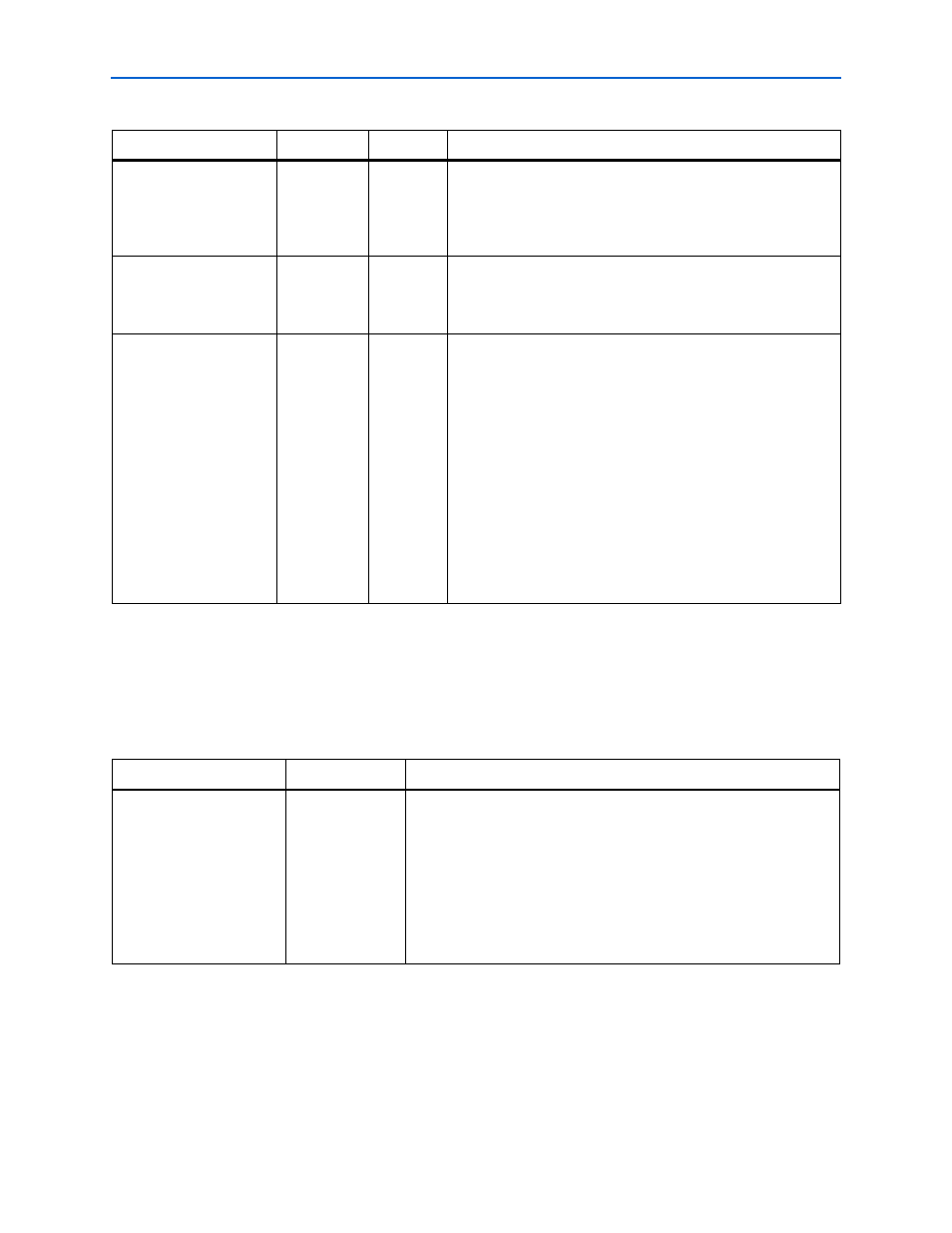
Table 3–12. Memory Property Parameters (Part 2 of 2)
(Note 1)
Parameter
Range
Units
Description
Table 3–13. Local Interface
Parameter
Range
Description
Local Interface
Native or Avalon
Specifies the local side interface between the user logic and the memory
controller, refer to
“Interface Description” on page 3–19
This interface refers to the connection of the user logic (driver) to the
controller. There are few differences between the two interfaces in
performing read and write transactions. The Avalon-MM interface is
supported by SOPC builder (refer
For non-SOPC builder designs, you can build the driver logic to interface
to the controller with either the native interface (refer to
) or the Avalon-MM interface.