Opencore plus time-out behavior, Opencore plus time-out behavior –3 – Altera DDR SDRAM Controller User Manual
Page 39
Chapter 3: Functional Description
3–3
OpenCore Plus Time-Out Behavior
© March 2009
Altera Corporation
DDR and DDR2 SDRAM Controller Compiler User Guide
IP Toolbench generates a clear-text VHDL or Verilog HDL datapath, which matches
your custom variation. If you are designing your own controller, Altera recommends
that you use this module as your datapath. IP Toolbench generates placement
constraints in the form of reusable scripts for all the critical registers in Cyclone series
and for the resynchronization registers in Stratix series. Altera recommends that you
also use these scripts so that your own DDR and DDR2 SDRAM designs have
consistent placement and the timing analysis script results apply to your design.
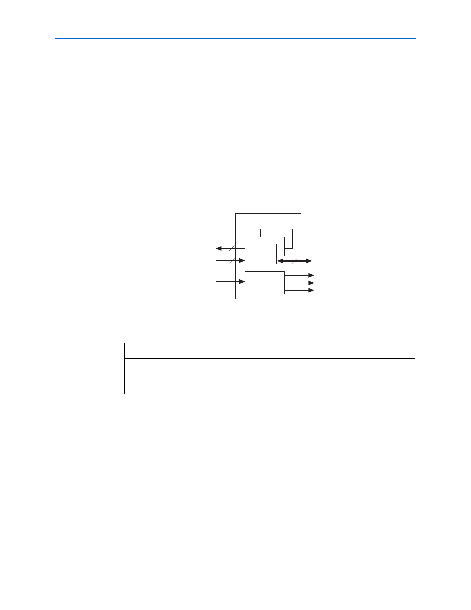
The datapath instantiates one or more data strobe (DQS) groups. The DQS group
module's control_wdata and control_rdata are fixed at 16 bits and data (DQ) is
fixed at 8 bits. To build datapaths larger than 16 bits, the datapath instantiates
multiple DQS group modules to increase the data bus width in increments of 16 bits
(8 bits for the DDR and DDR2 SDRAM side).
shows the datapath.
shows the IP Toolbench-generated datapath files in your project directory.
f
For more detail on the datapath, refer to
.
OpenCore Plus Time-Out Behavior
OpenCore Plus hardware evaluation can support the following two modes of
operation:
■
Untethered—the design runs for a limited time
■
Tethered—requires a connection between your board and the host computer. If
tethered mode is supported by all megafunctions in a design, the device can
operate for a longer time or indefinitely
Figure 3–2. Datapath
Table 3–2. Datapath Files
Filename
Description
Datapath.
Clock output generator.
DQS groups.
Data Path Module
control_rdata
control_wdata
dq
clk_to_sdram
DQS
Groups
16
8
16
clk
Clock Output
Generator
clk_to_sdram_n
fedback_clock_out