Altera DDR SDRAM Controller User Manual
Page 50
3–14
Chapter 3: Functional Description
Device-Level Description
DDR and DDR2 SDRAM Controller Compiler User Guide
© March 2009
Altera Corporation
For Stratix II devices, if you turn on the Use fed-back clock option and the Enable
DQS mode
option, you enable fed-back resynchronization, which uses a fed-back
clock to resynchronize the data captured by the DQS signal (refer to
). An additional resynchronization phase created by the main PLL transfers
the data back to the system clock.
Turning off Enable DQS mode enables fed-back capture mode. This mode uses a
fed-back clock to capture the read data and does not use the DQS strobe for capture
(refer to
). A resynchronization phase from the system PLL is
required to safely transfer the captured data to system clock phase. This mode offers
lower performance than fed-back resynchronization, but allows greater flexibility in
your choice of pins for DQ and DQS.
shows the recommended configuration for Stratix II devices.
f
For more information on non-DQS mode, refer to
shows the recommended configuration for Stratix and
Stratix GX devices.
1
The dqs_ref_clk input for Stratix or Stratix GX devices can be either fed-back from
the clock output driving the SDRAM or a separate clock output from the PLL. The
phase of dqs_ref_clk relative to the other clocks in the system is unimportant. The
controller switches off this input during reads, if you turn on Switch off Stratix DLL
reference clock during reads
(refer to
“Manual Timing Settings” on page A–1
).
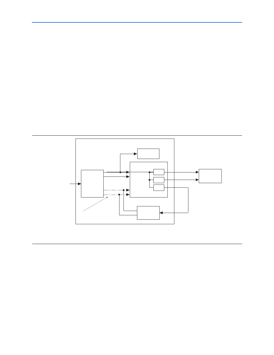
Figure 3–8. Stratix II PLL Configuration
Note to
(1) In most cases, clk or write_clk are used as the resynchronization and postamble clocks, therefore you need not use a separate clock output
from the PLL.
Optional
Fed-Back Clock
PLL
Note 1
Stratix II De
v
ice
DDR SDRAM
clk_to_sdram_n
clk_to_sdram
fedback_clock_out
DDR SDRAM
Controller
altddio
altddio
altddio
clock_source
Enhanced PLL
clk
write_clk
resynch_clk or
capture_clk
postamble_clk
C0
C1
C2
C3
Stratix II DLL