Altera DDR SDRAM Controller User Manual
Page 72
3–36
Chapter 3: Functional Description
Parameters
DDR and DDR2 SDRAM Controller Compiler User Guide
© March 2009
Altera Corporation
shows the memory controller options.
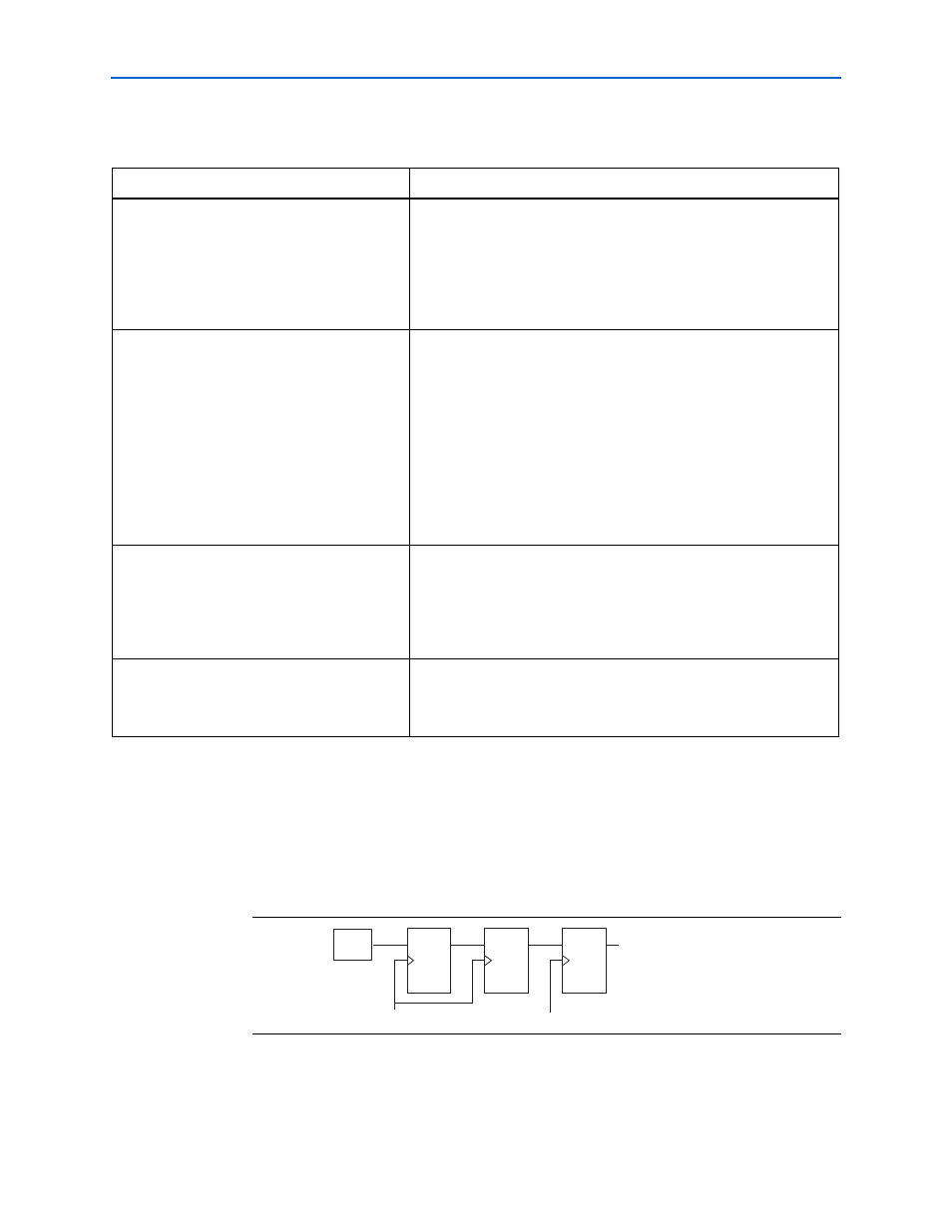
show the additional registers that you can specify with the
following memory controller options:
■
A = Insert pipeline registers on address and command outputs
■
B = Insert extra pipeline registers in the datapath
■
C = Clock address/command output registers on the negative edge
Table 3–16. Memory Controller Options
Parameter
Description
Insert pipeline registers on address and
command outputs
This register helps to achieve the required performance at frequencies >
200 MHz. When turned on, the wizard inserts a pipeline register stage
between the memory controller and the command and address outputs.
When this option is turned on an extra cycle (clk_to_sdram) of
latency is added between the time at which local_ready signal is
asserted at the local interface and the time the address or command
appears at the memory interface. Refer to
Insert extra pipeline registers in the datapath
This option is available only if you turn on Insert pipeline registers on
address and command outputs.
When turned on, the wizard inserts a second pipeline register stage
between the memory controller and the address and command outputs,
which results in an additional cycle (clk_to_sdram) of latency.
These registers are inserted in the clear-text datapath and the clock to
these registers is available as an input on your variation. These registers
help your design to meet higher internal clock frequency. The clock can
be adjusted if necessary. By default, it is connected to the system clock
and its edge is set by the Clock address/command output registers
on the negative edge option. Refer to
and
.
Clock address/command output registers on the
negative edge
When turned on, this option helps in meeting the setup and hold
requirements of the memory device for command and address with
respect to clock. However, you should perform your own timing
analysis of address/command timing. Generally, turn on this option,
except for Stratix II designs operating at 200 MHz or higher. Refer to
User controlled refresh
When turned on, you specify when auto-refresh commands are issued.
Otherwise, the controller issues regular auto-refresh commands at an
interval specified by tREFI, refer to
.
Figure 3–20. Additional Pipeline Registers—A = On, B = On, C= Off
addrcmd_clk
Positive Edge
Address and Command
Output
B
clk
FSM
A