Figure 3–14. reads – Altera DDR SDRAM Controller User Manual
Page 58
3–22
Chapter 3: Functional Description
Interfaces & Signals
DDR and DDR2 SDRAM Controller Compiler User Guide
© March 2009
Altera Corporation
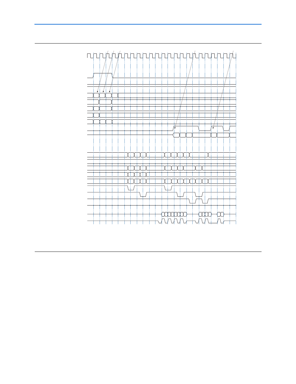
1. The user logic requests the first read by asserting the local_read_req signal,
and the size and address for this read. In this example, the request is a burst of
length 4 (8 on the DDR SDRAM side). The local_ready signal is asserted, which
indicates that the controller has accepted this request, and the user logic can
request another read or write in the following clock cycle. If the local_ready
signal was not asserted, the user logic must keep the read request, size, and
address signals asserted.
2. The user logic requests a second read to a different address, this time of size 2 (4
on the DDR SDRAM side). The local_ready signal remains asserted, which
indicates that the controller has accepted the request.
3. The user logic requests a third read to a different address, this time of size 1 (2 on
the DDR SDRAM side). The local_ready signal remains asserted, which
indicates that the controller has accepted the request.
Figure 3–14. Reads
Notes to
:
(1) The local_cs_addr, local_row_addr, local_bank_addr, and local_col_addr signals are a representation of the
local_addr
signal.
(2) DDR Command shows the command that the command signals are issuing.
clk
local_read_req
local_write_req
local_ready
local_size
local_cs_addr
(
1
)
local_row_addr
(
1
)
local_bank_addr
(
1
)
local_col_addr
(
1
)
local_rdata_valid
local_rdata
ddr_cs_n
ddr_cke
ddr_a
ddr_ba
DDR Command (
2)
ddr_ras_n
ddr_cas_n
ddr_we_n
ddr_dm
ddr_dq
ddr_dqs
0
4
2
1
0
0
0
1
0
1
170
040
000
040
0
1
0
1
050 055 057
000
057
5348
86F4 D310
77F4
0479
54B0
CB48
54B0
F
E
F
E
F
D
F
D
F
D
F
D
F
000
170 000 0A0
000
040 000 0AA
000
0AE
000
0AE
0
1
0
1
0
1
NOP
ACT
NOP
RD
NOP
ACT
NOP
RD
NOP
BT RD BT
NOP
BT
DDR SDRAM
Interface
Local Interface
[1]
[3]
[2]
[5]
[4]