Functional description, Block description, Control logic – Altera DDR SDRAM Controller User Manual
Page 37: Chapter 3. f, Block description –1, Control logic –1
© March 2009
Altera Corporation
DDR and DDR2 SDRAM Controller Compiler User Guide
3. Functional Description
The DDR and DDR2 SDRAM controllers instantiate an encrypted control logic and a
clear-text datapath. You can replace the control logic with your own custom logic.
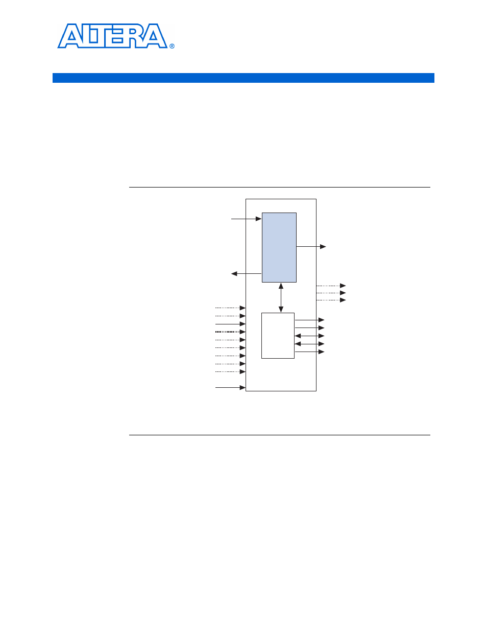
Block Description
shows a block diagram of the DDR & DDR2 SDRAM controller.
Control Logic
Bus commands control SDRAM devices using combinations of the ddr_ras_n,
ddr_cas_n
, and ddr_we_n signals. For example, on a clock cycle where all three
signals are high, the associated command is a no operation (NOP). A NOP command
is also indicated when the chip select signal is not asserted.
Figure 3–1. DDR & DDR2 SDRAM Controller Block Diagram
Notes to
:
(1) You can edit the ddr prefix on the SDRAM interfaces signals.
(2) DDR2 SDRAM controller only.
local_addr
local_be
local_burstbegin
local_read_req
local_refresh_req
local_size
local_wdata
local_write_req
ddr_a
ddr_ba
ddr_cas_n
ddr_cke
ddr_cs_n
ddr_odt (
2
)
ddr_ras_n
ddr_we_n
local_init_done
local_rdata
local_rdata_valid
local_rdata_valid_in_n
local_ready
local_refresh_ack
local_wdata_req
Control
Logic
(Encrypted)
ddr_dq
DDR SDRAM Controller
ddr_dm
ddr_dqs
Data Path
Module
(Clear Text)
clk
write_clk
fedback_clock_in
dqs_delay_ctrl[5:0]
resynch_clk
postamble_clk
capture_clk
resynch_
clk_edge_select
dqsupdate
addrcmd_clk
clk_to_sdram
clk_to_sdram_n
dqs_ref_clk
fedback_clock_out
stratix_dll_control