Interlogix NS3550-2T-8S User Manual User Manual
Page 141
IFS NS3552-8P-2S AND NS3550-2T-8S User Manual
141
Tagged packet entering VLAN 2
5.
While [PC-3] transmitting a tagged packet with VLAN Tag=2 enters Port-3, [PC-1] and [PC-2] will receive the
packet through Port-1 and Port-2.
6.
While the packet leaves Port-1 and Port-2, it will be stripped away its tag becoming an untagged packet.
Untagged packet entering VLAN 3
1.
While [PC-4] transmitting an untagged packet enters Port-4, the switch will tag it with a VLAN Tag=3. [PC-5] and
[PC-6] will receive the packet through Port-5 and Port-6.
2.
While the packet leaves Port-5, it will be stripped away its tag becoming an untagged packet.
3.
While the packet leaves Port-6, it will keep as a tagged packet with VLAN Tag=3.
For this example, just set VLAN Group 1 as default VLAN, but only focus on VLAN 2 and VLAN 3 traffic
flow
Setup steps
1. Create VLAN Group
Set VLAN Group 1 = Default-VLAN with VID (VLAN ID) =1
Add two VLANs – VLAN 2 and VLAN 3
VLAN Group 2 with VID=2
VLAN Group 3 with VID=3
2. Assign VLAN Member :
VLAN 2 : Port-1, Port-2 and Port-3
VLAN 3 : Port-4, Port-5 and Port-6
VLAN 1: All other ports – Port-7~Port-24
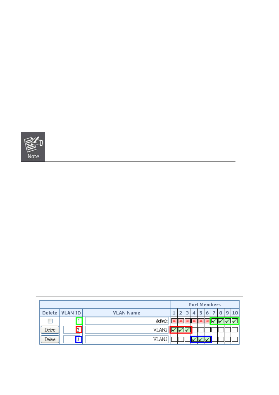
3. Remove VLAN Member for VLAN 1:
Remember to remove Port 1 – Port 6 from VLAN 1 membership, since Port 1 – Port 6 has been assigned to VLAN 2 and
VLAN 3.
Figure 4-6-9: Add new VLAN group, assign VLAN members to VLAN 2 and VLAN 3 and remove specified ports from VLAN 1
member