Timing chart, Chapter 7 i/o terminals – KEYENCE LS-7600 User Manual
Page 159
7-11
Chapter 7 I/O Terminals
7
Timing Chart
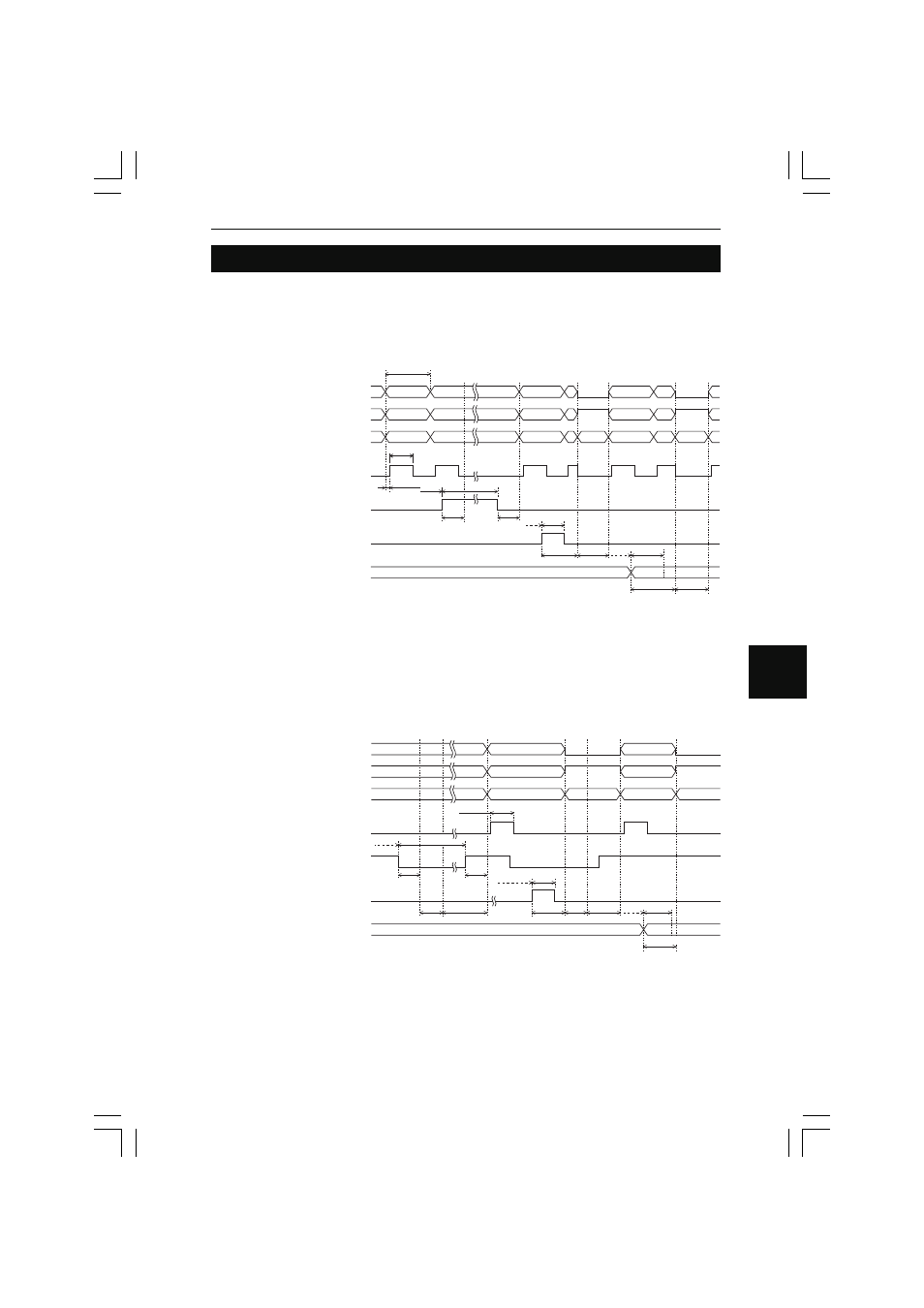
This section provides information on the timing charts of BCD output in a variety of meas-
uring modes.
■
Normal, Auto Peak Hold, Auto Bottom Hold, and Auto Peak-to-peak
Hold
ON
OFF
TIMING input
ON
OFF
RESET/ZERO input
ON
OFF
P1 input to P4 input
ON
OFF
Comparator output
ON
OFF
WAITING output
ON
OFF
ON
OFF
STROBE output
BCD output
Refresh cycle
STROBE time
0
±
0.1ms
Min
Min2.1ms
Min2.1ms
Max2.5ms
RESET
time
Max2.5ms
Max2.5ms
2.1ms
Min
2.1ms
Min6.0ms
Max12.0ms
Min
6.0ms
RESET
time
• The refresh cycle and reset time vary with the setting of the averaging number.
Refer to Reset Time and Refresh Cycle on page 7-13 for detail.
• The strobe output time can be changed. If the time set exceeds the refresh cycle time,
the strobe output will be always ON.
Refer to Strobe Output Time on page 5-47 for detail.
■
Peak Hold, Bottom Hold, Peak-to-peak Hold, Average Hold, and
Sample Hold 1
ON
OFF
TIMING input
ON
OFF
RESET/ZERO input
ON
OFF
P1 input to P4 input
ON
OFF
Comparator output
ON
OFF
WAITING output
ON
OFF
ON
OFF
STROBE output
BCD output
STROBE time
0
±
0.1ms
Min2.1ms
Min
2.1ms
Min2.1ms
Min2.1ms
Max2.5ms RESET
time
RESET
time
Sampling
period
Sampling
period
Max2.5ms
Max2.5ms
Min6.0ms
Min
6.0ms
Max12.0ms
• The strobe output time can be changed.
Refer to Strobe Output Time on page 5-47 for detail.
• Reset time varies with the setting of the averaging number.
Refer to Reset Time and Refresh Cycle on page 7-13 for detail.
• When RESET input turns ON, the internal measured value will be determined with an
elapse of reset time.