Caution – KEYENCE LS-7600 User Manual
Page 153
7-5
Chapter 7 I/O Terminals
7
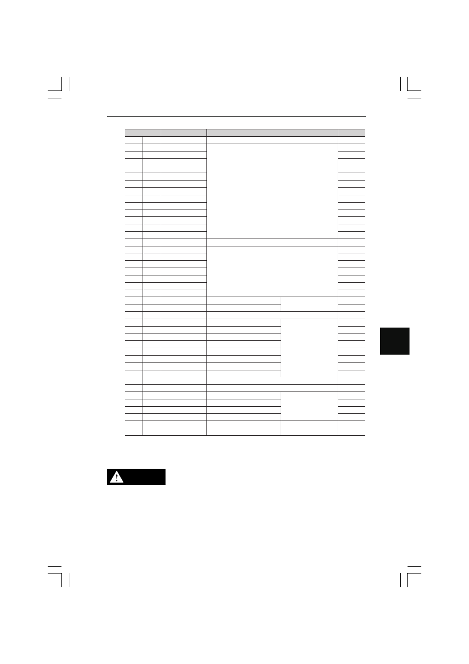
SUB Mode
Terminal number
Cable color
Signal name
Description
1
2
3
4
5
6
7
8
9
10
11
12
13
14
15
16
17
18
19
20
21
22
23
24
25
26
27
28
29
30
31
32
33
34
35
36
37
38
39
40
Brown
Red
Orange
Yellow
Green
Blue
Purple
Gray
White
Black
Brown
Red
Orange
Yellow
Green
Blue
Purple
Gray
White
Black
Brown
Red
Orange
Yellow
Green
Blue
Purple
Gray
White
Black
Brown
Red
Orange
Yellow
Green
Blue
Purple
Gray
White
Black
COM2
(Not used)
(Not used)
(Not used)
(Not used)
(Not used)
(Not used)
(Not used)
(Not used)
(Not used)
(Not used)
(Not used)
(Not used)
(Not used)
COM2
(Not used)
(Not used)
(Not used)
(Not used)
(Not used)
(Not used)
(Not used)
OUT1 STATS RUN
OUT2 STATS RUN
(Not used)
AREA2 FUNCTION
OUT2 HH
OUT2 HI
OUT2 GO
OUT2 LO
OUT2 LL
OUT2 WAITING
OUT2 STROBE
COM2
(Not used)
OUT2 TIMING
OUT2 RESET
OUT2 ZERO
OUT2 STATS
AREA1 FUNCTION
Connector I/O common
Connector I/O common
OUT1 statistical processing output
OUT2 statistical processing output
AREA2 function output
OUT2 HH output
OUT2 HI output
OUT2 GO output
OUT2 LO output
OUT2 LL output
OUT2 waiting output
OUT2 strobe output
Connector I/O common
OUT2 timing input
OUT2 RESET input
OUT2 auto zero input
OUT2 statistical processing input
AREA1 function output
NPN open collector output
➾
See page 7-10
Non-voltage input
➾
See page 7-9
NPN open collector
output
➾
See page 7-10
NPN open collector output
➾
See page 7-10
❈
Terminals 1, 8, and 37 share the COM2 signal in common.
❈
The cable colors correspond to OP-26505.
• The 0-V power supply, COM1, and COM2 signals are common
in voltage through a choke coil each. Check that there is no
potential difference between them.
• All unused terminals must be open. Do not connect any wires
to them, otherwise the LS-7600 Series may malfunction.
CAUTION