Reference schematic, Sata port esata port, Com express interfaces – Kontron COMe Starterkit Eval T2 User Manual
Page 89: Picmg, Com express
COM Express Interfaces
2.10.2.
Reference Schematic
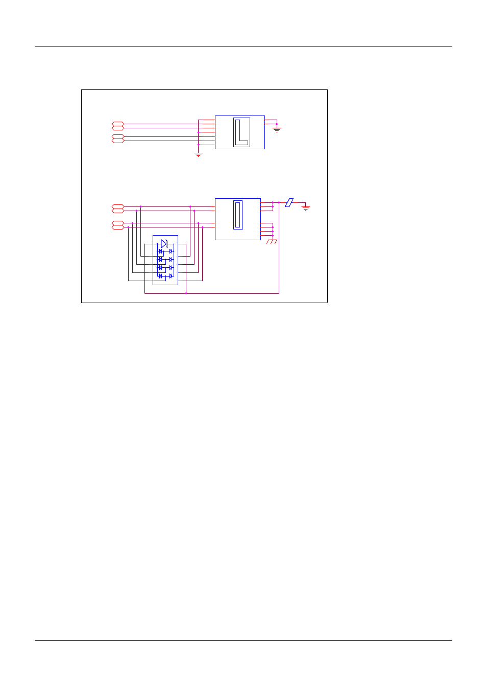
Figure 33:
SATA Connector Diagram
The following notes apply to Figure 33 above.
The Module provides a single LED signal SATA_ACT# that can be used to indicate SATA drive
activity.
The SATA connector shown is a Molex 67491 series, a 1.27mm-pitch 7-pin high-speed vertical
plug.
The example design contains the SATA data and ground signals only. Power is provided through
a separate connector from the system power supply. Alternate 22-pin connector types are
available that deliver power and data to the SATA drive. This may be over a combined
power/data cable or in a direct configuration in which the SATA drive mates directly to the 22-pin
plug on the Carrier Board. Please refer to the SATA specification (Appendix G) for pin-out
information.
ESD clamp diodes such as Semtech Rclamp0524 are shown in the eSATA schematic. This
device contains low capacitance clamp diodes. The schematic shows two connections on each
SATA signal to the clamp diodes. The second connection is actually a no-connect on the
package and allows for straight-through routing for the SATA differential pairs.
Nets SATA0_TX+/- through SATA1_TX +/- are sourced from the COM Express Module SATA TX
pins.
Nets SATA0_RX+/- through SATA1_RX +/- are sourced from SATA disks and are routed to the
COM Express Module SATA RX pins.
Coupling capacitors are not needed on Carrier Board SATA lines. They are present on the COM
Express Module.
PICMG
®
COM Express
®
Carrier Board Design Guide
Rev. 2.0 / December 6, 2013
89/218
CEX
SATA0_TX+
CEX
SATA0_TX-
CEX
SATA0_RX+
CEX
SATA0_RX-
CEX
SATA1_TX-
CEX
SATA1_RX+
CEX
SATA1_RX-
CEX
SATA1_TX+
SATA Port
eSATA Port
D6
TVS Diode Array_3
D6
TVS Diode Array_3
1
9
3
4
6
8
10
2
7
5
J8
J8
GND0
1
TX+
2
TX-
3
GND1
4
RX-
5
RX+
6
GND2
7
Shield0
8
Shield1
9
Shield2
10
Shield3
11
FB47
50-Ohms@100MHz 3A
FB47
50-Ohms@100MHz 3A
J7
Con_SATA
J7
Con_SATA
GND0
1
TX+
2
TX-
3
GND1
4
RX-
5
RX+
6
GND2
7
MNT1
S1
MNT2
S2
eSATA