General purpose serial interface, Signal definitions – Kontron COMe Starterkit Eval T2 User Manual
Page 125
COM Express Interfaces
2.20.
General Purpose Serial Interface
Since Revision 2.0 of the COM Express specification two optional serial ports are available on
Type 10 and Type 6 COM Express Modules uses pins on the A-B connector that have been
reclaimed from the A-B VCC_12V pool. As such, it is possible that if a Type 6 or 10 Module is
deployed in an R1.0 Carrier Board for Module Types 1,2,3,4,5 then the Module TTL level serial
pins may be exposed to the 12V supply, and Module designers must plan for this. Similarly, an
R1.0 Module deployed on an R2.0 Carrier may bridge 12V to the serial pins and Carrier
designers must plan for this. These pins are designated SER0_TX, SER0_RX, SER1_TX and
SER1_RX. Data out of the Module is on the _TX pins. Please refer to section 2.22.10
'Protecting COM.0 Pins Reclaimed From the VCC_12V Pool' on page 144 below. Hardware
handshaking and hardware flow control are not supported.
2.20.1.
Signal Definitions
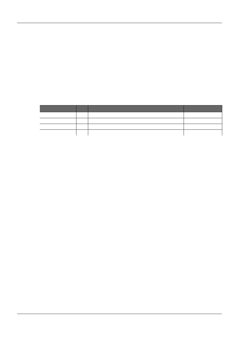
Table 39:
General Purpose Serial Interface Signal Definition
Signal
Pin
Description
I/O
SER0_TX
A98
Transmit Line for Serial Port 0
O CMOS (protected)
SER0_RX
A99
Receive Line for Serial Port 0
I CMOS (protected)
SER1_TX
A101
Transmit Line for Serial Port 1 (can be shared with CAN function) O CMOS (protected)
SER1_RX
A102
Receive Line for Serial Port 1 (can be shared with CAN function)
I CMOS (protected)
In Revision 2.0 of COM Express Specification these signals have been reclaimed from the
VCC_12V pool. Therefore protection on the Module and on the Carrier Board is necessary to
avoid damage to those when accidentally exposed to 12V.
PICMG
®
COM Express
®
Carrier Board Design Guide
Rev. 2.0 / December 6, 2013
125/218